Supercharge Your Innovation With Domain-Expert AI Agents!

Image processing device, image processing method, and program

An image processing device and color image technology, which can be used in image communication, television, electrical components, etc., and can solve problems such as reduced prediction accuracy

Active Publication Date: 2013-12-04
SONY GRP CORP
View PDF7 Cites 18 Cited by
  • Summary
  • Abstract
  • Description
  • Claims
  • Application Information

AI Technical Summary

Problems solved by technology

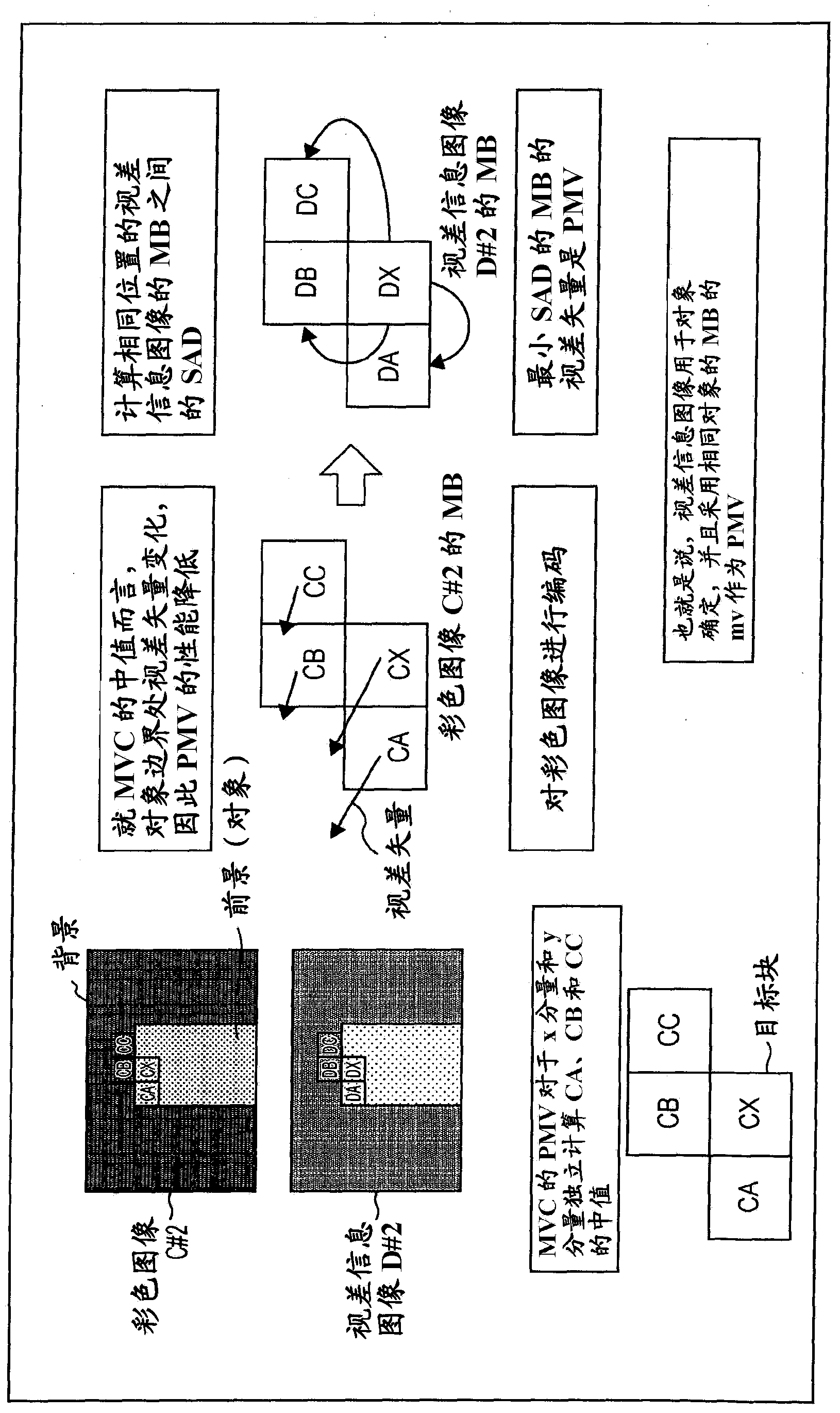
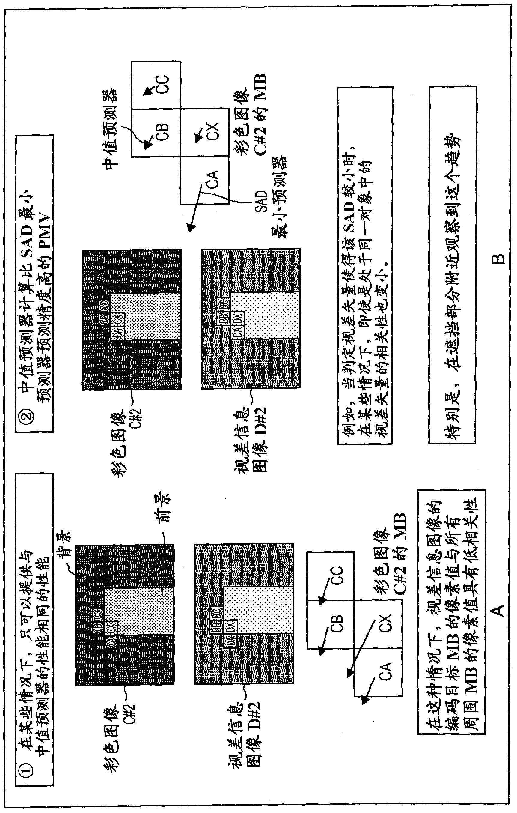
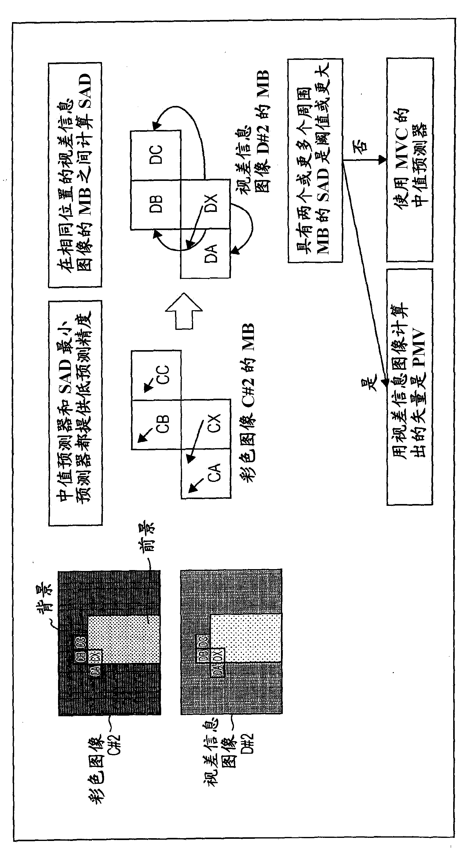
[0013] According to the MVC standard, although the predicted motion vector (of the disparity vector) of the target block is calculated using the disparity vectors of the blocks surrounding the target block of the color image, when the target block is in the boundary part of the foreground object, the foreground block, background block and Blocks in the part where there is occlusion exist as surrounding blocks of this target block, so the predicted motion vector of the target block calculated with these blocks causes a decrease in prediction accuracy in some cases

Method used


Image

  • Image processing device, image processing method, and program
  • Image processing device, image processing method, and program
  • Image processing device, image processing method, and program

Examples


Embodiment Construction

[0078] [Description of depth image (disparity information image) in this manual]

[0079] Figure 44 is a view illustrating parallax and depth.

[0080] like Figure 44 As shown in , when a color image of the subject M is taken with the camera c1 arranged at the position C1 and the camera c2 arranged at the position C2, the depth Z of the subject M is defined according to the following equation (a), namely, Distance from camera c1 (camera c2) in depth direction.

[0081] Z=(L / d)×f…(a)

[0082] In addition, L is the distance between the position C1 and the position C2 in the horizontal direction (hereinafter, referred to as “inter-camera distance”). In addition, d is the value obtained by subtracting the distance u2 from the distance u1 (that is, the parallax), and the distance u2 is the distance between the position of the subject M on the color image captured by the camera c2 in the horizontal direction and the center of the color image , the distance u1 is the distance ...


PUM


Abstract

The present technique relates to an image processing device, an image processing method and a program which can calculate a vector which is precisely predicted as a predicted motion vector of a disparity vector. A predicted motion vector generation unit 243 generates a predicted motion vector of a disparity vector which represents a disparity of a target block of an operation target of a viewpoint #2 color image C#2 different from a point of view #1 with respect to a color image C#1 of the point of view #1, from a disparity information image D#2 of the point of view #2 which has disparity information related to a disparity of each pixel of the color image C#2 of the point of view #2 as a pixel value according to a depth information use prediction standard. The present invention is applicable to, for example, generate a predicted motion vector of a disparity vector used to generate a predicted image upon encoding or decoding of a plurality of viewpoint images.

Description

technical field [0001] The present technology relates to an image processing device, an image processing method, and a program, and more specifically, to an image processing device, an image processing method, and a program that can calculate an accurately predicted motion vector as a predicted motion vector of a disparity vector Represents the disparity of a given viewpoint image relative to another viewpoint image. Background technique [0002] Encoding standards for encoding multiple viewpoint images such as 3D (dimensional) images include, for example, the MVC (Multi-View Video Coding) standard obtained by extending the AVC (Advanced Video Coding) (H.264 / AVC) standard. [0003] According to the MVC standard, an encoding target image is a color image in which a value corresponding to light from a subject is used as a pixel value, and if necessary, other viewpoint color images are referred to in addition to this viewpoint color image to a plurality of viewpoint color image...

Claims


Application Information

Patent Timeline
Patent Type & Authority Applications(China)
IPC IPC(8): H04N7/32H04N13/00
CPCH04N19/00278H04N19/00218H04N19/00884H04N19/00696H04N13/0048H04N19/00769H04N19/597H04N19/52H04N19/159H04N19/176H04N19/70H04N13/161
Inventor 高桥良知服部忍
Owner SONY GRP CORP
Features
  • R&D
  • Intellectual Property
  • Life Sciences
  • Materials
  • Tech Scout
  • Unparalleled Data Quality
  • Higher Quality Content
  • 60% Fewer Hallucinations
Learn More