
Adjustable positioning device

A technology of positioning device and circumferential position, which is applied in the direction of workpiece clamping device, worktable, manufacturing tools, etc., can solve the problems of cost increase and inconvenient use, and achieve the effect of cost reduction

Inactive Publication Date: 2013-12-11
SUZHOU TOPO ELECTRICAL & MECHANICAL TECH
View PDF6 Cites 6 Cited by
  • Summary
  • Abstract
  • Description
  • Claims
  • Application Information

AI Technical Summary

Problems solved by technology

[0002] The use of vacuum cleaners has brought great convenience to household cleaning, so that people no longer worry about cleaning every day, so they have entered thousands of households. In order to ensure the reliability of product quality and the safety of people when using it, it is necessary to To test each part of the vacuum cleaner, different parts need to have different positioning frames, which will increase the cost and make it inconvenient to use

Method used


Image

  • Adjustable positioning device

Examples


Embodiment Construction

[0017] The specific implementation manners of the present invention will be further described in detail below in conjunction with the accompanying drawings and embodiments. The following examples are used to illustrate the present invention, but are not intended to limit the scope of the present invention.

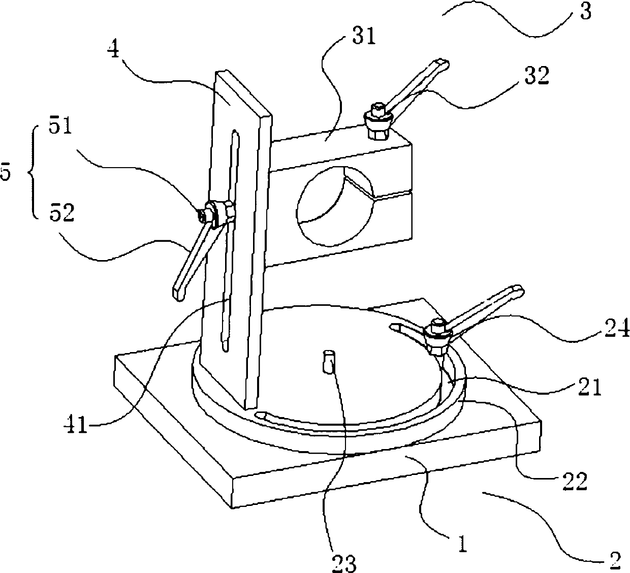
[0018] Such as figure 1 As shown, the positioning device includes: a base 1, and the base 1 is provided with a circumferential rotation assembly 2 for adjusting the horizontal circumferential position. The circumferential rotation assembly 2 includes a rotating disk 22, and the rotation The disc 22 is provided with a semicircular limiting hole 21, and the semicircular limiting hole 21 is provided with a first fixing member 24 for fixing the rotating disc 22, and the vertical position above the rotating disc 22 is A limit plate 4 is directly arranged, and a waist-shaped limit hole 41 is provided in the center of the limit plate 4;

[0019] The positioning device also incl...


PUM


Abstract

The invention discloses an adjustable positioning device, and belongs to detection equipment of dust collector parts. The positioning device comprises a base. A circumferential direction rotation assembly is arranged on the base and used for adjusting positions in horizontal and circumferential directions. The positioning device further comprises a vertical adjusting assembly which is arranged on a limiting hole and used for adjusting the position in the vertical direction. The positioning device can achieve adjustment at different angles and positions, detects various parts, is more convenient and fast to use, and reduces cost.

Description

technical field [0001] The invention relates to vacuum cleaner component detection equipment, in particular to an adjustable positioning device. Background technique [0002] The use of vacuum cleaners has brought great convenience to household cleaning, so that people no longer worry about cleaning every day, so they have entered thousands of households. In order to ensure the reliability of product quality and the safety of people when using it, it is necessary to To detect each part of the vacuum cleaner, different parts need to have different positioning frames, which will cause an increase in cost and inconvenience in use. Contents of the invention [0003] (1) Technical problems to be solved [0004] The technical problem to be solved by the present invention is to provide an adjustable positioning jig which saves time and labor and has a good effect when adjusting the height of the part to be tested. [0005] (2) Technical solution [0006] In order to solve the ...

Claims


Application Information

Patent Timeline
IPC IPC(8): B25B11/00B25H1/10
Inventor 范秉昊
Owner SUZHOU TOPO ELECTRICAL & MECHANICAL TECH
Learn More