Suspension Mechanism for Additional Conductors of Catenary in Electrification of High Speed ​​Railway

A high-speed railway and suspension mechanism technology, applied in the direction of overhead lines, etc., can solve the problems of insufficient strength, achieve the effects of flexible rotation, elimination of air gap discharge, and novel ideas

Active Publication Date: 2016-04-06
陕西万里达铁路电气化器材有限公司
View PDF10 Cites 0 Cited by
  • Summary
  • Abstract
  • Description
  • Claims
  • Application Information

AI Technical Summary

Problems solved by technology

[0003] The purpose of the present invention is to provide a high-speed railway electrified catenary additional wire suspension mechanism that is simple in structure, wear-resistant, and fully meets the installation and use requirements of high-speed electrified railways. Large, forming defects such as electrical corrosion

Method used


Image

  • Suspension Mechanism for Additional Conductors of Catenary in Electrification of High Speed ​​Railway
  • Suspension Mechanism for Additional Conductors of Catenary in Electrification of High Speed ​​Railway

Examples


Embodiment Construction

[0013] The present invention will be further described below in conjunction with the accompanying drawings and embodiments.

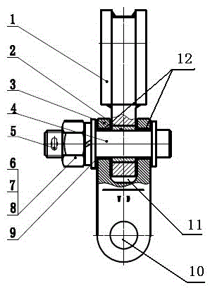
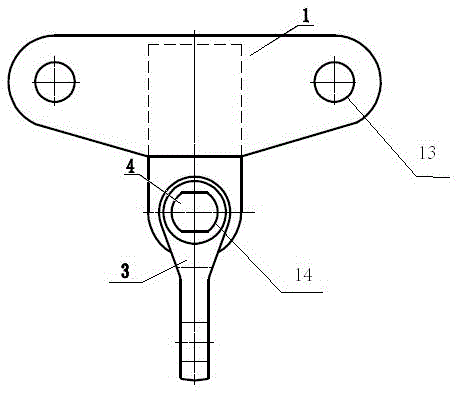
[0014] Such as figure 1 and figure 2 As shown, the additional wire suspension mechanism of the electrified catenary of high-speed railway is characterized in that: it includes a double-eared connecting plate 1 and a single and double-eared vertical connecting plate 3; both ends of the double-eared connecting plate 1 have double ears and two ear holes 13 and a first connection hole 14, the upper two ear holes 13 are respectively located on the two ears at both ends, the middle part of the ears is an empty groove and symmetrical to the left and right, the first connection hole 14 below is located on the line of symmetry, and the first connection 14 holes are inlaid with the second A bearing sleeve 2; the lower end of the single and double ear vertical connecting plate 3 has a second connecting hole 10, and the upper end has a U-shaped groove 11 perpendi...


PUM


Abstract

The invention belongs to the technical field of manufacturing of parts of a high-speed railway electrified contacting net, and particularly relates to an additional wire suspension mechanism for the high-speed railway electrified contacting net. The additional wire suspension mechanism is characterized by comprising a double-lug yoke plate and a single-double-lug vertical yoke plate, wherein both ends of the double-lug yoke plate are provided with double lugs, and the double-lug yoke plate is provided with two lug holes and a first connecting hole; the two lug holes at the upper part are respectively positioned on the two lugs at both the ends; the middle parts of the two lugs are of an empty slot structure and are laterally symmetrical; the first connecting hole at the lower part is positioned on the symmetric line; a first bearing bushing is embedded in the first connecting hole; the lower end of the single-double-lug vertical yoke plate is provided with a second connecting hole, and the upper end of the single-double-lug vertical yoke plate is provided with a U-shaped groove vertical to the second connecting hole; both ends of the U-shaped groove are respectively provided with through holes; the centers of the through holes at both the ends are positioned on the same center line; second bearing bushings are embedded into the through holes at both the ends; a connecting hinge pin passes through the first bearing bushing and the second bearing bushings; both ends outside through holes at both ends of the connecting hinge pin are fixed by fasteners. The additional wire suspension mechanism has a simple structure, has wear resistance and is particularly suitable for heavy-wind zones.

Description

technical field [0001] The invention belongs to the technical field of high-speed railway electrification catenary component manufacturing, and in particular relates to a high-speed railway electrification catenary additional wire suspension mechanism. technical background [0002] The existing device is composed of double-ear connecting plate and ZS-7Z right-angle hanging plate, which forms a section of vortex wind in the strong wind area, and the wind direction and impact force acting on the suspension point of the additional wire are random, and the suspension point is affected by turbulence. The weightlessness of the thread causes intermittent contact between the double lug plate and the ZS-7Z right-angle hanging plate, and a gap is formed between the bolt and the bolt hole during the swing of the thread, which is equivalent to forming an air gap capacitor, causing discharge and electrical corrosion , Accelerate the aging of the parts, thereby increasing the wear of the ...

Claims


Application Information

Patent Timeline
Patent Type & Authority Patents(China)
IPC IPC(8): B60M1/20
Inventor 王兴全韩佳栋田志军王玉环王琪
Owner 陕西万里达铁路电气化器材有限公司
Why Eureka
Try Eureka