Pressure roller assembly

A technology of components and pressure rollers, applied in the field of pressure roller components, can solve the problems of inaccurate positioning and transmission, back and forth movement, left and right movement of conveyed objects, etc., and achieves the effect of good effect, simple structure and reasonable design.

Inactive Publication Date: 2013-12-11
黄平
View PDF9 Cites 0 Cited by
  • Summary
  • Abstract
  • Description
  • Claims
  • Application Information

AI Technical Summary

Problems solved by technology

[0002] The pressure roller mainly plays the role of extrusion, positioning and transmission. The existing pressure roller is mainly composed of a connecting rod and a roller. The roller rotates on the connecting rod. However, in order to ensure the flexibility of the rotation of the roller, there is a large gap between the roller and the connecting rod. The roller may move back and forth in the gap when it is rolling, causing the object to be conveyed to move left and right, and the positioning and transmission are inaccurate

Method used


Image

  • Pressure roller assembly

Examples


Embodiment Construction

[0010] In order to make the technical means, creative features, goals and effects achieved by the present invention easy to understand, the present invention will be further described below in conjunction with specific illustrations.

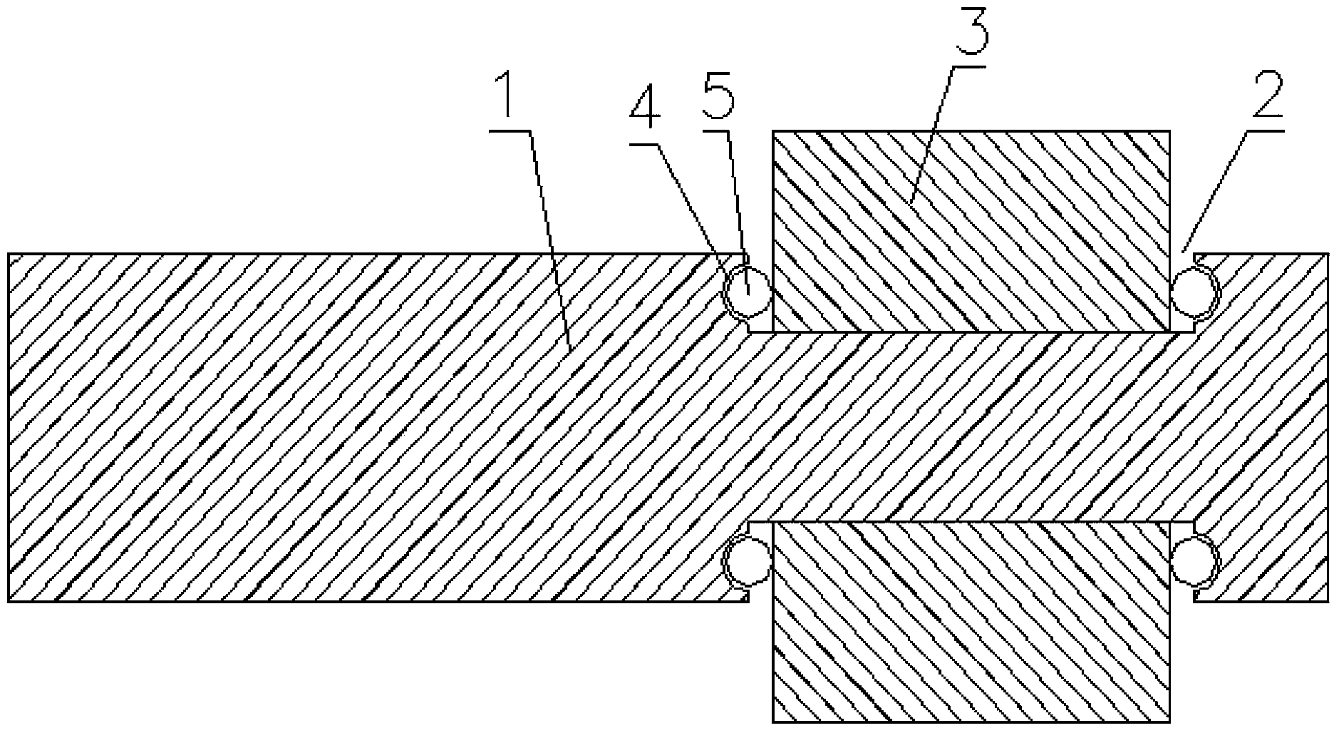
[0011] Such as figure 1 The pressure wheel assembly shown includes a connecting rod 1, a groove 2 is provided on the connecting rod 1, a roller 3 is set on the groove 2, and an inwardly recessed hemispherical groove 4 is provided on both sides of the groove 2, and the hemispherical groove Steel ball 5 is placed in 4, and steel ball 5 tops on the side of roller 3, wherein hemispherical groove 4 circles around the side of groove 2, and hemispherical groove 4 on the groove communicates with hemispherical groove 4 to form an annular hemispherical groove.

[0012] The basic principles, main features and advantages of the present invention have been shown and described above. Those skilled in the industry should understand that the present invention ...


PUM


Abstract

The invention discloses a pressure roller assembly with adjustable rotating speed and relates to the field of pressure rollers. The pressure roller assembly comprises a connecting rod, wherein the connecting rod is stepped, and comprises a primary connecting rod and a secondary connecting rod; a roller is sleeved on the secondary connecting rod; the front end of the secondary connecting rod is provided with a screw thread; the screw thread is in threaded connection with a choke plug. The pressure roller assembly has the advantages of simple structure, reasonable design, easiness, practicability and remarkable effect; the roller is extruded by using the mobility of the chock plug, so that the rotating flexibility of the roller is lowered to control the rotating speed of the roller.

Description

Technical field: [0001] The invention relates to the technical field of pressure rollers, in particular to a pressure roller assembly. Background technique: [0002] The pressure roller mainly plays the role of extrusion, positioning and transmission. The existing pressure roller is mainly composed of a connecting rod and a roller. The roller rotates on the connecting rod. However, in order to ensure the flexibility of the rotation of the roller, there is a large gap between the roller and the connecting rod. The roller may move back and forth in the gap when rolling, causing the object to be conveyed to move left and right, and the positioning and transmission are inaccurate. Invention content: [0003] The technical problem to be solved by the present invention is to overcome the defects of the prior art and provide a roller support with compact structure and accurate positioning and transmission of the pressure rollers. [0004] The technical problem to be solved by th...

Claims


Application Information

Patent Timeline
Patent Type & Authority Applications(China)
IPC IPC(8): B65G47/22B65H9/04B65H23/038
Inventor 黄平
Owner 黄平
Why Eureka
Try Eureka