A clamping device for a reaction tank

A clamping device and reaction tank technology, which is applied in the direction of transportation and packaging, conveyor objects, etc., can solve the problems of increased production costs, broken reaction tanks, high damage rate of reaction tanks, etc.

Active Publication Date: 2015-09-30
LUOYANG ZHONGYE HEAVY IND GRP CO LTD
View PDF8 Cites 0 Cited by
  • Summary
  • Abstract
  • Description
  • Claims
  • Application Information

AI Technical Summary

Problems solved by technology

Because the reaction tank itself has a certain weight, for the tank unloader, the reaction tank clamping device also entrains and supports the direct reduced iron with a certain weight on the inner wall of the reaction tank after the chemical reaction at the same time, so it is necessary to apply very Only a large clamping force can hold and lift the reaction tank, and too large clamping force can easily crush the reaction tank, resulting in a very high damage rate of the reaction tank, which will increase the production cost

Method used


Image

  • A clamping device for a reaction tank
  • A clamping device for a reaction tank
  • A clamping device for a reaction tank

Examples


Embodiment approach

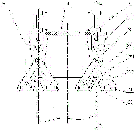
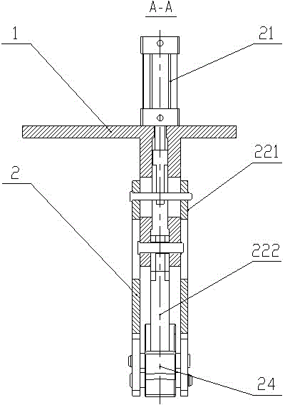
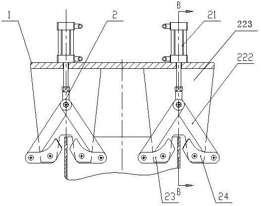
[0023] Such as figure 1 with figure 2 In the first specific embodiment shown, the connecting piece 22 includes a fixed plate 223, two connecting rods 222 and a push plate 221, the fixed plate 223 is fixedly connected with the hanger 1, and one end of the two connecting rods 222 is fixed to the The plate 223 is hinged, and the other end is respectively hinged with one end of the outer jaw 24 and the inner jaw 23; the other end of the outer jaw 24 and the inner jaw 23 is connected with the air cylinder or hydraulic cylinder 21 through the push plate 221, the specific embodiment Using a cylinder, the cylinder drives the outer jaw 24 and the inner jaw 23 to rotate around the pin shafts of the outer jaw 24, the inner jaw 23 and the two connecting rods 222 by driving the push plate 221, thereby realizing the outer jaw 24 and the inner jaw. The jaws 23 clamp or loosen the wall of the reaction tank.

[0024] The push plate 221 is made of a rectangular or trapezoidal steel plate, th...


PUM


Abstract

A clamping device for a reaction tank, including a hanger and several clamping mechanisms, the clamping mechanism is suspended on the hanger and distributed on the circumference corresponding to the wall of the reaction tank, the clamping mechanism includes an air cylinder or a hydraulic cylinder, a connecting Parts, outer jaws and inner jaws, the outer jaws and inner jaws are symmetrically located on the outer wall and inner wall of the reaction tank respectively, the air cylinder or hydraulic cylinder is connected with the inner jaws and the outer jaws through the connecting piece, and drives the connecting piece The corresponding components in the drive the outer and inner jaws to clamp or loosen the reaction vessel wall. According to the present invention, the cylinder or the hydraulic cylinder drives the outer jaws and the inner jaws so that the clamping parts of the inner jaws and the outer jaws are engaged on the inner and outer walls of the reaction tank. Under the action of the gravity of the items inside the tank, the friction force of the clamping parts of the inner jaws and outer jaws on the inner and outer walls of the reaction tank is increased, thereby clamping the reaction tank, avoiding the The phenomenon that the reaction tank is damaged by inward pressure.

Description

technical field [0001] The invention relates to an accessory device of a direct reduced iron production line, in particular to a clamping device of a reaction tank. Background technique [0002] The production process of the prior art direct reduced iron production line is: the mixture of iron powder and reducing agent is pressed into a cylindrical reduction block by a briquetting hydraulic forming machine, and the block machine puts the cylindrical reduction block on the kiln car according to the columnar shape, and then The canning machine uses its reaction tank clamping device to set the reaction tank on the cylindrical reduction block, and the kiln car filled with the cylindrical reduction block and the outer reaction tank is sent into the tunnel kiln for roasting. The cylindrical reduction block After the chemical reaction in the reaction tank, the volume expands to support the inner wall of the reaction tank. After the roasting is completed, the cylindrical reduction ...

Claims


Application Information

Patent Timeline
Patent Type & Authority Patents(China)
IPC IPC(8): B65G47/90
Inventor 陈德军仝站国张凤林
Owner LUOYANG ZHONGYE HEAVY IND GRP CO LTD
Why Eureka
Try Eureka