Device for electrolytically depositing nickel or cobalt

An electrowinning and electrowinning cell technology, which is applied in the field of electrolytic deposition equipment, achieves the effects of low electrical energy consumption, shortening the same-pole spacing, and saving production costs

Inactive Publication Date: 2013-12-11
四川省尼科国润新材料有限公司
View PDF4 Cites 5 Cited by
  • Summary
  • Abstract
  • Description
  • Claims
  • Application Information

AI Technical Summary

Problems solved by technology

In the existing electrolytic cell structure, the cell voltage is above 4.0V, the power consumption is high, and the cell utilization factor is not satisfactory
Due to the consumption of a considerable number of diaphragm bags and diaphragm frames during the electrowinning process, the difficulty of the hoisting process is increased, and the labor intensity of the workers is increased
overall increased cost

Method used


Image

  • Device for electrolytically depositing nickel or cobalt
  • Device for electrolytically depositing nickel or cobalt
  • Device for electrolytically depositing nickel or cobalt

Examples


Embodiment 1

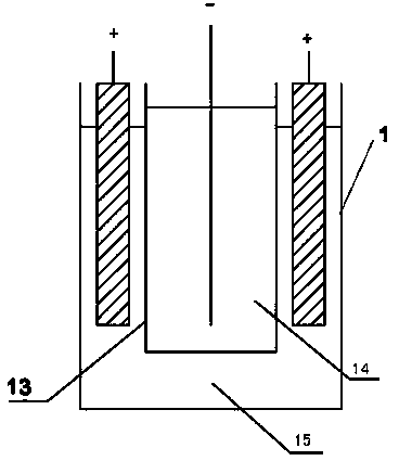
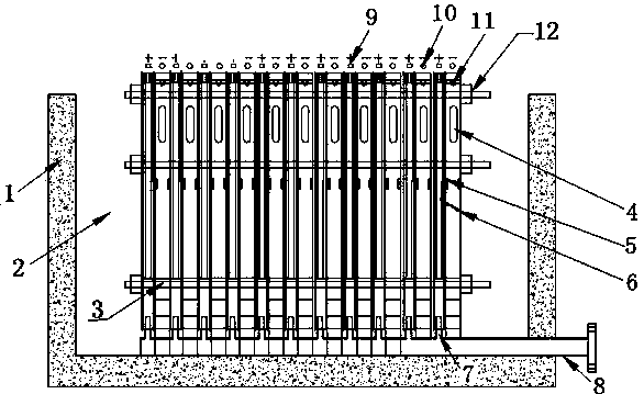
[0022] As shown in the figure, the device for electrowinning nickel or cobalt includes an electrowinning cell with a cathode frame and an anode frame. In the electrowinning cell, the number of cathode frames is one less than the number of anode frames. In the electrowinning cell One end is provided with a high-level tank, and the electrolyte in the high-level tank enters the electrowinning cell through the pipeline. Since the catholyte inlet is set on the cathode frame, the electrolyte in the electrowinning cell enters the cathode frame through the catholyte inlet. A permeable membrane with appropriate permeability is set between the anode frame and the anode frame, so the electrolyte enters the anode frame at a constant speed through the permeable membrane to complete the entire electrowinning process. , the acid mist discharge outlet is set on the upper end of the anode frame, so the anolyte produced is discharged out of the electrowinning cell through the anolyte outlet, and...

Embodiment 2

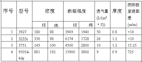
[0026] Adopt the electrowinning cell structure in embodiment 1, keep consistent with the size and the length of the electrowinning cell in the comparative example, set the quantity of the cathode sheet in the cathode frame in the electrowinning cell to be 34, and the pole spacing is 100mm, adopts model as 3751 polyester cloth is used as the permeable membrane between the cathode frame and the anode frame, the liquid level difference between the liquid level in the cathode frame and the liquid level in the anode frame is kept at 18 mm, the cell voltage is 3.0 / V, and the output is 0.454 t / slot·day, DC power consumption is 4050Kw·h.

Embodiment 3

[0028] The electrowinning cell structure in Example 1 is adopted, and the size and length of the electrowinning cell in the comparative example are kept consistent. The number of cathode sheets in the cathode frame in the electrowinning cell is set to 48, the pole spacing is 70mm, and the model is 3751. The polyester cloth is used as the permeable membrane between the cathode frame and the anode frame, and the liquid level difference between the liquid level in the cathode frame and the liquid level in the anode frame is kept at 20mm, and the obtained cell voltage is 2.5 / V, and the output It is 0.655t / slot·day, and the DC power consumption is 3645Kw·h.


PUM


Abstract

The invention relates to electrolytic deposition equipment and in particular to a device for electrolytically depositing nickel or cobalt. According to the device, a cathode frame and an anode frame are arranged in an electrodeposition cell; a permeable membrane is arranged between the cathode frame and the anode frame; an overhead tank is arranged at one end of the electrodeposition cell; electrolyte in the overhead tank is connected with the electrodeposition cell through a pipeline; an electrolyte inlet is formed in the cathode frame; electrolyte in the electrodeposition cell enters the cathode frame through the electrolyte inlet formed in the cathode frame; the electrolyte permeates into the anode frame through the permeable membrane; a lower tank is arranged at the other end of the electrodeposition cell; an anode liquor outlet is formed in the lower end of the anode frame; the anode liquor flows into a branch pipe through the anode liquor outlet, is converged through an anode liquor convergence header pipe, then enters an anode liquor overflow opening after convergence and is connected with the lower tank to be discharged out of the electrodeposition cell through the pipeline. The condition that the cathode and the anode are separated by means of a diaphragm frame in the traditional technology is changed, the homopolar distance in the electrodeposition cell is greatly shortened, and the tank utilization rate is improved. The electric energy consumption is low, and the production cost is reduced.

Description

technical field [0001] The invention relates to electrolytic deposition equipment in the technical field of chemical industry, in particular to a device for electrodepositing nickel or cobalt. [0002] Background technique [0003] The structure of the electrolytic cell includes the cell body, anode and cathode. Electrolytic nickel or electrolytic cobalt is also called insoluble anode electrolytic extraction of nickel or insoluble anode electrolytic extraction of cobalt. The process is carried out in a diaphragm electrolytic cell with nickel sulfate as the electrolyte. Example: The purified pure nickel sulfate solution continuously flows into the diaphragm bag of the cathode chamber of the diaphragm electrolyzer (commonly known as the cathode chamber), and then continuously percolates outward through the diaphragm to the anode region, commonly known as the anolyte, and is finally discharged from the outlet of the electrolyzer. A diaphragm frame supporting the cathode is ar...

Claims


Application Information

Patent Timeline
Patent Type & Authority Applications(China)
IPC IPC(8): C25C1/08C25C7/00C25C7/04
Inventor 邓智林杨思增干勇
Owner 四川省尼科国润新材料有限公司
Why Eureka
Try Eureka