Intake manifold performance detection device and detection method
A technology of intake manifold and detection device, which is applied in the field of intake manifold performance detection device and intake manifold performance detection, which can solve the problem of traceability, increase the difficulty of research and development and detection of intake manifold, and the fluctuation of detection value Larger issues
- Summary
- Abstract
- Description
- Claims
- Application Information
AI Technical Summary
Problems solved by technology
Method used
Image
Examples
Embodiment 1
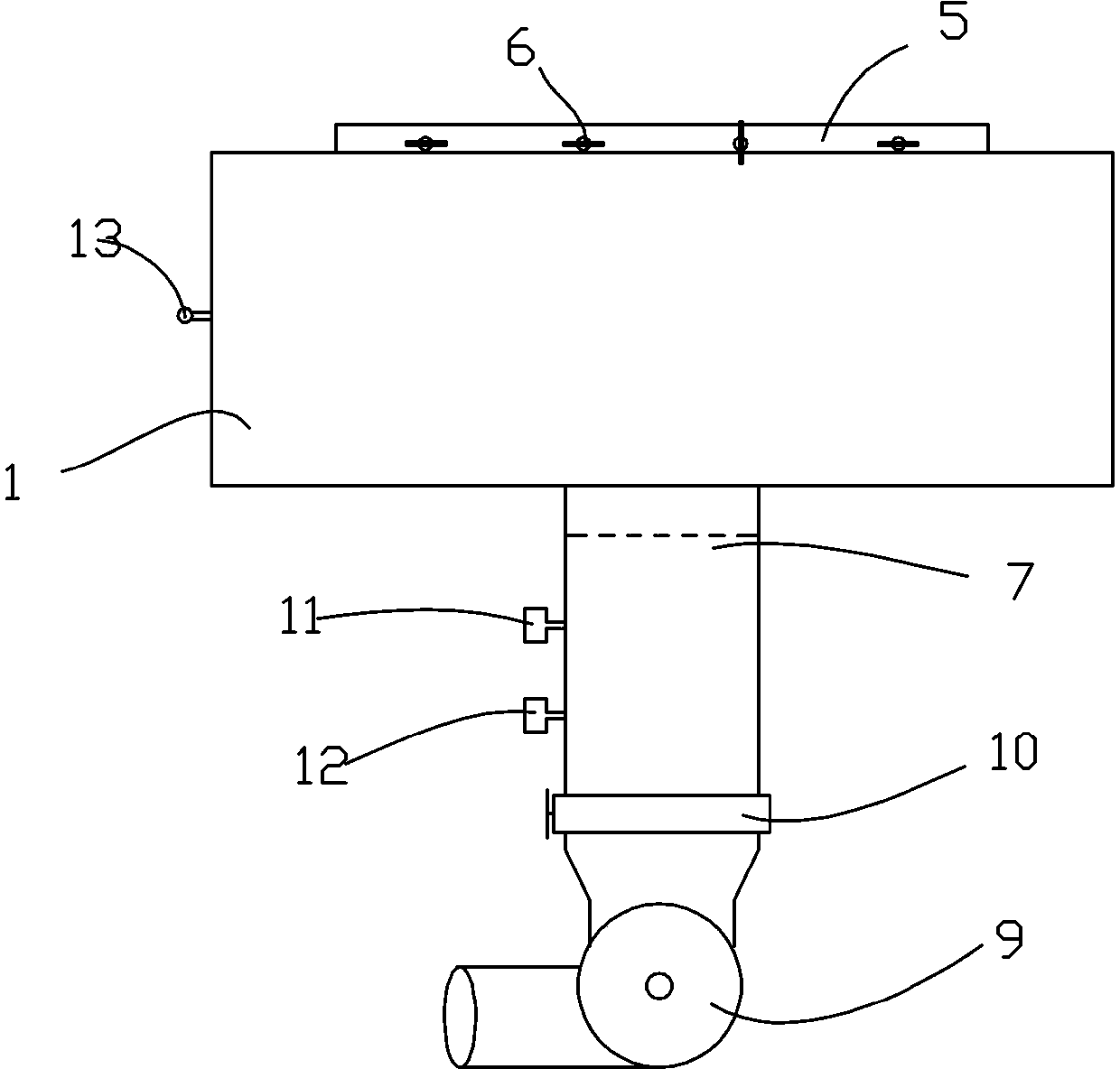
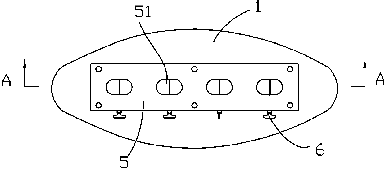
[0033] This embodiment relates to an intake manifold performance detection device, which consists of Figure 1 to Figure 3 As shown, it includes a plenum chamber 1, a manifold connecting plate 5 arranged on the upper surface of the plenum chamber 1, and an air outlet pipe 7 arranged on the lower surface of the plenum chamber 1, which is connected to the plenum chamber 1 in the air outlet pipe 7 A vortex generator 8 is arranged at the place, a vacuum blower 9 is connected to the end of the outlet pipe 7, a valve 10 for controlling the opening and closing of the outlet pipe 7 is arranged on the outlet pipe 7 near the vacuum fan 9, and a valve 10 for controlling the opening and closing of the outlet pipe 7 is arranged on the outlet pipe 7. A vortex flow meter 11 and a flow meter 12 for detecting the gas in the gas outlet pipe 7 are also provided on the plenum chamber 1 with a vacuum gauge 13 for detecting the internal vacuum degree.
[0034] The structure of the manifold connecti...
Embodiment 2
[0038] This embodiment relates to a method for detecting the performance of an intake manifold, which includes the following steps:
[0039] Step a, make all the control valves 6 rotate to the closed state, turn on the vacuum fan 9 to evacuate the plenum chamber 1, when the vacuum gauge 13 shows that the vacuum degree reaches 10KPa, close the valve 10, and let it stand for a period of time to test the plenum chamber 1 tightness;
[0040] Step 1, one of the control valves 6 is opened, so that the air flow in the intake manifold branch corresponding to the control valve 6 enters the plenum chamber 1;
[0041] Step 2, when the airflow in the plenum chamber 1 is discharged from the air outlet pipe 7, the vortex generator 8 converts the airflow into a vortex;
[0042] Step 3, through the vortex flow meter 11 and the flow meter 12, the degree and flow rate of the vortex formed in the air outlet pipe 7 are detected respectively;
[0043] Step 4, repeat steps 1 to 3 to complete the ...
PUM
 Abstract
Description
Claims
Application Information
 - R&D
- Intellectual Property
- Life Sciences
- Materials
- Tech Scout
- Unparalleled Data Quality
- Higher Quality Content
- 60% Fewer Hallucinations
Browse by: Latest US Patents, China's latest patents, Technical Efficacy Thesaurus, Application Domain, Technology Topic, Popular Technical Reports.
© 2025 PatSnap. All rights reserved.Legal|Privacy policy|Modern Slavery Act Transparency Statement|Sitemap|About US| Contact US: help@patsnap.com


