System for testing fatigue crack propagation in corrosion environment

A technology of fatigue crack growth and test testing, which is applied in the direction of testing the ductility of materials, and can solve the problems of low precision fatigue crack growth performance testing and lack of cracks

Inactive Publication Date: 2013-12-11
BEIHANG UNIV
View PDF6 Cites 22 Cited by
  • Summary
  • Abstract
  • Description
  • Claims
  • Application Information

AI Technical Summary

Problems solved by technology

At present, the test of crack growth performance at home and abroad mainly relies on manual observation and recording through magnifying glass marking. The accuracy is low and it is difficult t

Method used


Image

  • System for testing fatigue crack propagation in corrosion environment
  • System for testing fatigue crack propagation in corrosion environment
  • System for testing fatigue crack propagation in corrosion environment

Examples


specific Embodiment approach 1

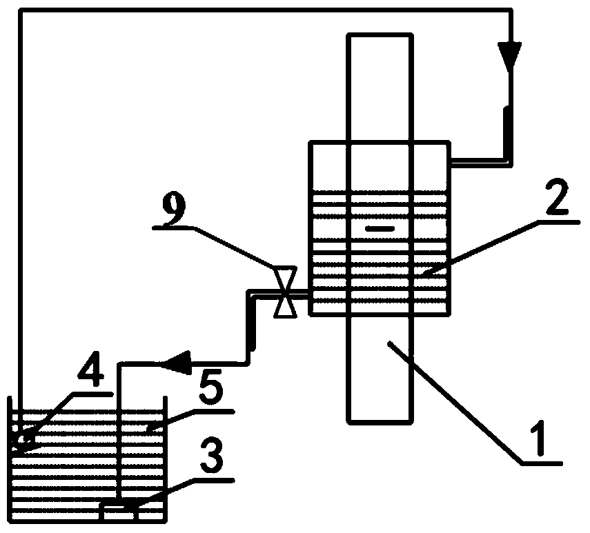
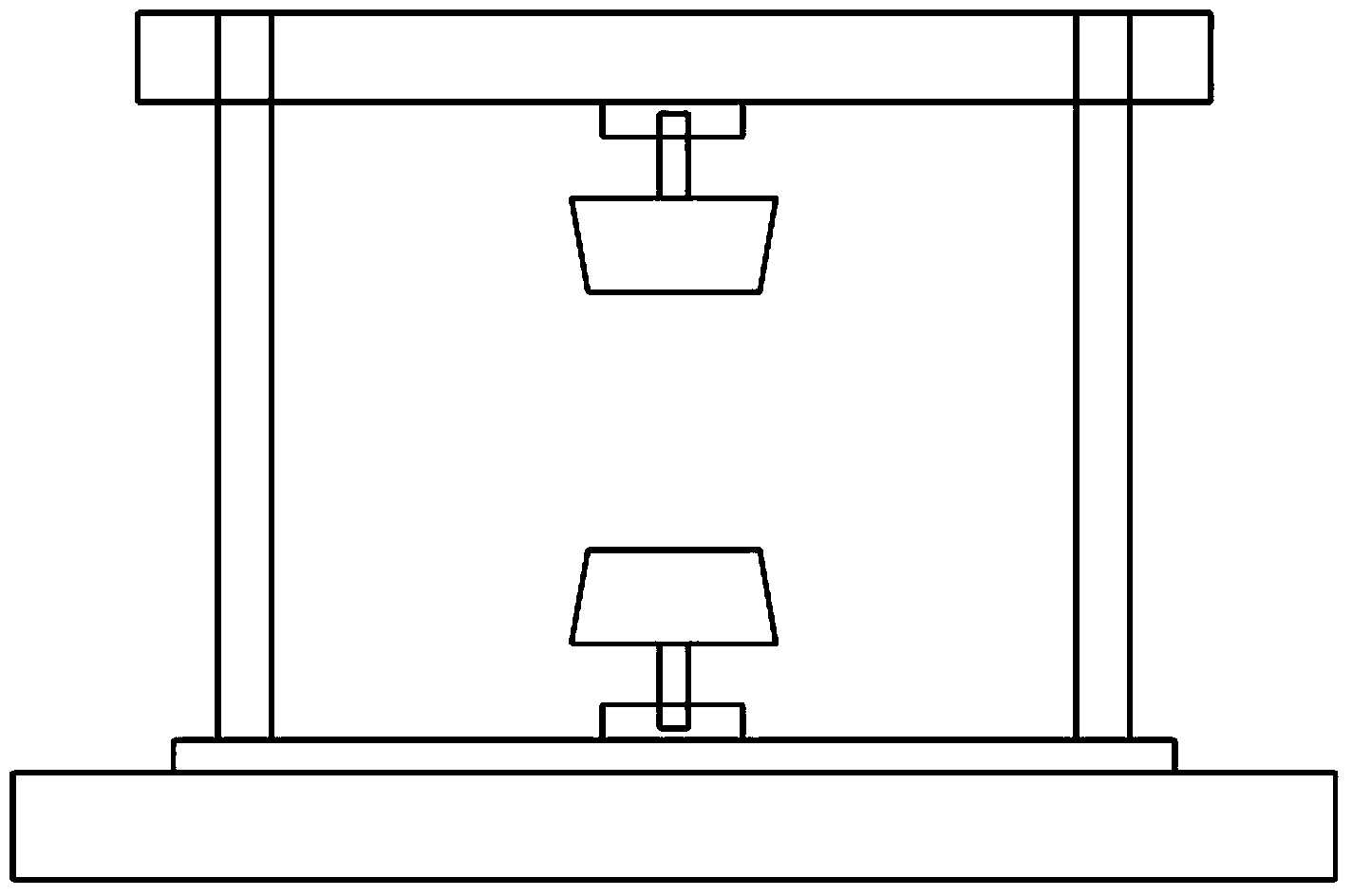
[0022] Specific implementation mode one: combine Figure 1 to Figure 4 Specific embodiments of the present invention will be described.

[0023] The present invention is a fatigue crack growth test system in a corrosive environment, which consists of a fatigue testing machine 7, a medium box 2, a solution circulation pump 4, a filter 3, a flow control valve 9, a solution tank 5, a fixture 8, and a crack observation system 6 and sample 1 composition. The connection relationship between them is as follows: the sample 1 is installed on the fixture 8, and the fixture 8 is connected to the fatigue testing machine 7; The circulation pump 4 transports the corrosion solution filtered by the filter 3 from the solution tank 5 to the medium box 2, and the solution in the medium box 2 flows back to the solution box 5 after the flow rate is controlled by the flow control valve 9; the crack observation system 6 passes The microscope records the crack growth by computer. The test system f...

specific Embodiment approach 2

[0032]Embodiment 2: The difference between this embodiment and Embodiment 1 lies in the design of sample 1. Sample 1 can be a plate with or without holes in the center, and the size parameters can be the same as those in Embodiment 1. The sample 1 can be in the shape of a rod or other structural forms, and the other design ideas and connection methods of the test system for fatigue crack growth test in a corrosive environment are the same as those in the first embodiment.

specific Embodiment approach 3

[0033] Specific embodiment 3: The difference between this embodiment and specific embodiment 1 lies in the design of the corrosion solution. The corrosion solution can use NaCl brine solution of other concentrations, or other components of the corrosion solution. Fatigue crack growth test under corrosive environment Other design concepts and connection methods of the test system are the same as those in the first embodiment.


PUM


Abstract

A system for testing fatigue crack propagation in a corrosion environment comprises a fatigue testing machine, a medium box, a solution circulating pump, a filter, a flow control valve, a solution tank, a clamp, a crack observing system and a test sample, wherein the test sample is mounted on the clamp, the clamp is connected with the fatigue testing machine, the medium box is arranged on the test sample in a sleeving manner, so that the liquid level of the solution is higher than the to-be-observed part of the test sample, the solution circulating pump conveys an etchant solution filtered by the filter to the medium box from the solution tank, the solution in the medium flows back to the solution tank after the flow speed of the solution is controlled by the flow control valve, and the crack observing system with a microscope records the crack propagation condition through a computer. The system for testing the fatigue crack propagation in the corrosion environment is scientific in conception, simple in structure and convenient in operation and can be used to test the fatigue crack propagation property in the corrosion environment, and the test result has a great important engineering application value for assessing the damage tolerance of a material and a structure in the corrosion environment.

Description

technical field [0001] The invention relates to a fatigue crack growth test system in a corrosive environment, which belongs to the technical field of test and test. Background technique [0002] Engineering materials and structures are subjected to alternating loads during use, and fatigue damage may occur. In order to ensure their safety, it is necessary to test their fatigue performance. After years of technological development, a complete fatigue performance testing standard has been formed; engineering materials and Structures are also often used in corrosive environments. For example, aircraft and ships serving in coastal or offshore environments are corroded by seawater and salt spray for a long time. Therefore, their corrosion fatigue crack growth performance must be measured to evaluate their corrosion fatigue cracks. Extended life. At present, the test of crack growth performance at home and abroad mainly relies on manual observation and recording through magnifyi...

Claims


Application Information

Patent Timeline
IPC IPC(8): G01N3/28
Inventor 熊峻江王池权刘牧东
Owner BEIHANG UNIV
Why Eureka
Try Eureka