Method and device for switching network device from stand-by state to main state and network device

A network device and state switching technology, applied in the field of communication, can solve problems affecting user experience, wrong switching of network devices, prolonged switching time, etc.

Active Publication Date: 2013-12-11
TONGDING INTERCONNECTION INFORMATION CO LTD
View PDF5 Cites 7 Cited by
  • Summary
  • Abstract
  • Description
  • Claims
  • Application Information

AI Technical Summary

Problems solved by technology

If the detection time of BFD is set too short, there will be a risk of mistaken switching of network devices in the standby state when a single link fails; if the detection time of BFD is set too long, double-point faults or active When a network device fails, the switching time of the network device in the standby state will be prolonged, which will affect the user experience

Method used


Image

  • Method and device for switching network device from stand-by state to main state and network device
  • Method and device for switching network device from stand-by state to main state and network device
  • Method and device for switching network device from stand-by state to main state and network device

Examples


Embodiment 1

[0104] Such as Figure 5 As shown, there are four states that a layer-3 network device may be in: main state, standby state, standby upgrade to the main delay state, and delay execution of the operation that the layer-3 network device is in the main state. For a layer-3 network device running VRRP :

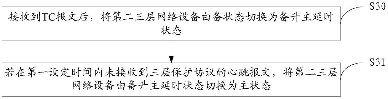
[0105] When in the standby state, if a TC message is received, it will switch to the standby upgrade master delay state. Even if the BFD detection result is DOWN, it will not switch to the master state; If the VRRP heartbeat message sent by the network device or the detection result of BFD is in the UP state within twice the detection period, the standby state will be released, and the Layer 3 network device will be switched from the standby state to the standby state. . If the TC message is not received, and the VRRP heartbeat message is not received within the first set time or the BFD detection result is in the DOWN state, the Layer 3 network device will be directly switched...

Embodiment 2

[0111] Such as Figure 6As shown, there are four states that a layer-3 network device may be in: main state, standby state, standby upgrade to the main delay state, and delay execution of the operation that the layer-3 network device is in the main state. For a layer-3 network device running PIM :

[0112] When in the standby state, if a TC message is received, it will switch to the standby upgrade master delay state. Even if the subsequent BFD detection result is DOWN state, it will not switch to the master state; If the PIM HELLO message sent by the network device or the detection result of BFD is in the UP state within twice the detection period, the backup master delay state will be released, and the Layer 3 network device will be switched from the backup master delay state to the standby state. If the TC message is not received, and the PIM HELLO message is not received within the first set time, then the Layer 3 network device will be directly switched from the backup m...


PUM


Abstract

The invention provides a method and device for switching a network device from a stand-by state to a main state and the network device. The method and device are applied to a network comprising a three-layer network and a two-layer ring network. A first three-layer network device and a second three-layer network device of the three-layer network are connected with a two-layer network device in the two-layer ring network, and a three-layer protection protocol is operated. The first three-layer network device is in the main state, and the second three-layer network device is in the stand-by state. The method comprises the steps that after a TC message is received, the second three-layer network device is switched from the stand-by state to a stand-by-to-main delay state, and if a heartbeat message of the three-layer protection protocol is not received within a first set time period, the second three-layer network device is switched from the stand-by-to-main delay state to the main state. Through the scheme, the second three-layer network in the stand-by state can be prevented from being switched to the main state mistakenly.

Description

technical field [0001] The invention relates to the technical field of communication, in particular to a method and device for switching network equipment from a standby state to a main state, and the network equipment. Background technique [0002] With the development of Internet technology and the popularization of network applications, the number of Internet users is increasing step by step, and the Metropolitan Area Network (MAN) emerges as the times require. MAN generally has a tree or ring structure. The layer network is separated. Such as figure 1 Shown is a schematic diagram of a ring-shaped MAN. Network devices 10 and 11 are egress nodes of the MAN, which are layer-3 network devices. Layer-3 protection protocols are deployed on network devices 10 and 11, such as Virtual Router Redundancy Protocol (Virtual Router Redundancy Protocol, VRRP), Protocol Independent Multicast (PIM), etc.; Layer 2 ring network access network devices 10, 11, Layer 2 ring network is compo...

Claims


Application Information

Patent Timeline
IPC IPC(8): H04L12/773H04L12/713H04L12/741H04L45/586H04L45/74
Inventor 张耀坤赵全喜
Owner TONGDING INTERCONNECTION INFORMATION CO LTD
Why Eureka
Try Eureka