LED radiator

A technology of LED radiators and heat sinks, which is applied in lighting and heating equipment, cooling/heating devices of lighting devices, lighting devices, etc., and can solve problems such as difficulty in dissipating heat from radiators, poor cooling effect, and reduced service life of LED light sources. , to achieve good heat dissipation effect, avoid accumulation, uniform and good heat dissipation effect

Active Publication Date: 2013-12-18
爱博特电子(宁波)集团有限公司
View PDF4 Cites 2 Cited by
  • Summary
  • Abstract
  • Description
  • Claims
  • Application Information

AI Technical Summary

Problems solved by technology

[0003] However, since the heat sinks are all arranged within the range of the heat dissipation substrate, the bottom of the heat dissipation passage between the heat dissipation fins is closed by the heat dissipation substrate, and no upper and lower air circulation passages are formed in the heat dissipation passage. After absorbing heat, the air density decreases and rises to leave the heat dissipation channel, while the lower temperature air below the heat dissipation channel is blocked by the heat dissipation substrate and cannot enter the heat dissipation channel, making it difficult to dissipate the heat of the radiator, and the heat dissipation effect is poor. The working temperature can reach 80°C-90°C. In addition, because there are partitions at both ends of the heat dissipation substrate, the heat dissipation channel is closed by the partition plate, which is extremely difficult to clean, and the LED lamps are in the outdoor environment for a long time, and a large amount of dust and debris accumulate in the heat dissipation channel Among them, these dust and debris make the heat dissipation effect of the radiator worse, causing the LED light source to still work in a high temperature environment, reducing the service life of the LED light source

Method used


Image

  • LED radiator
  • LED radiator

Examples


Embodiment

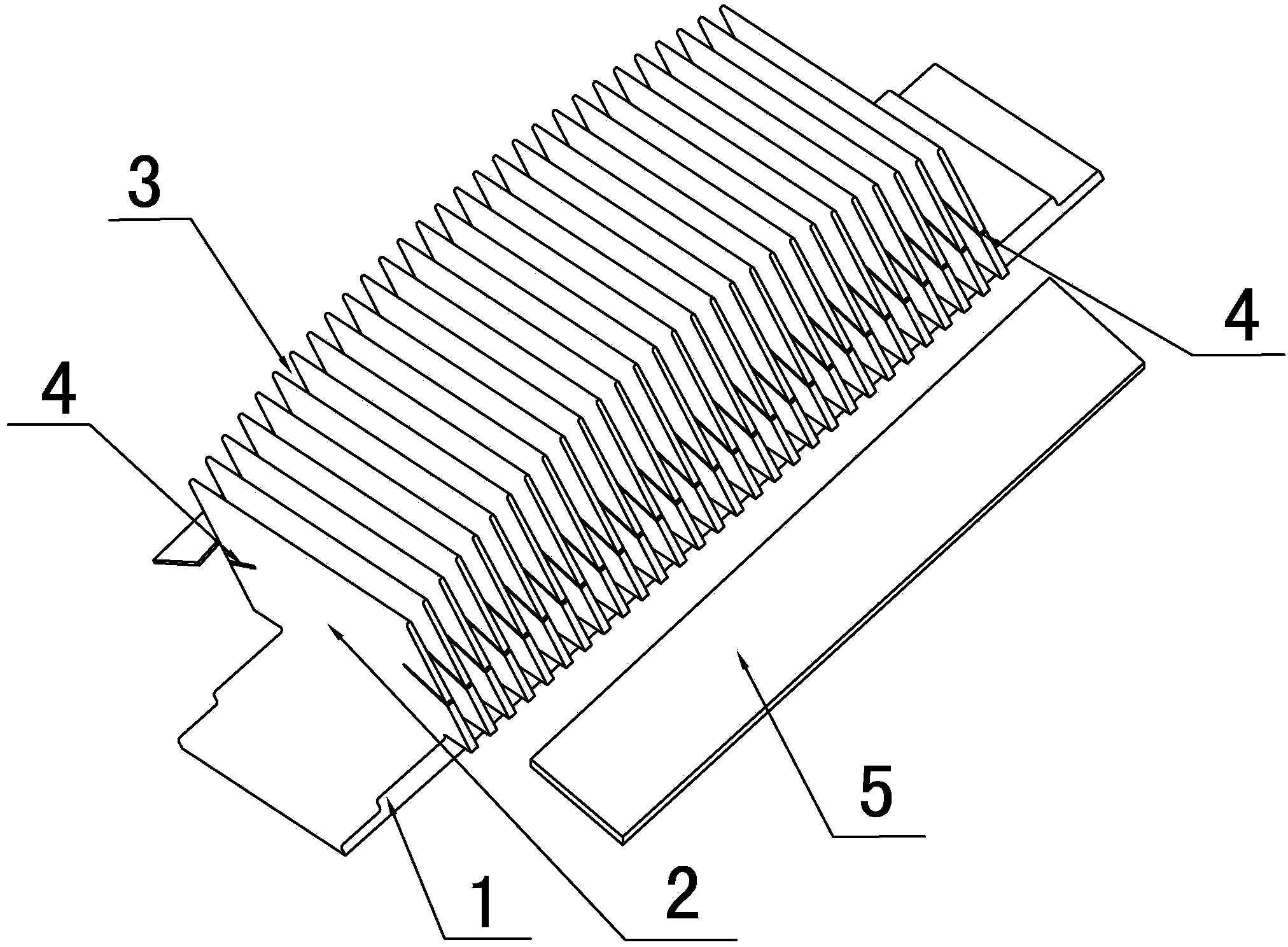
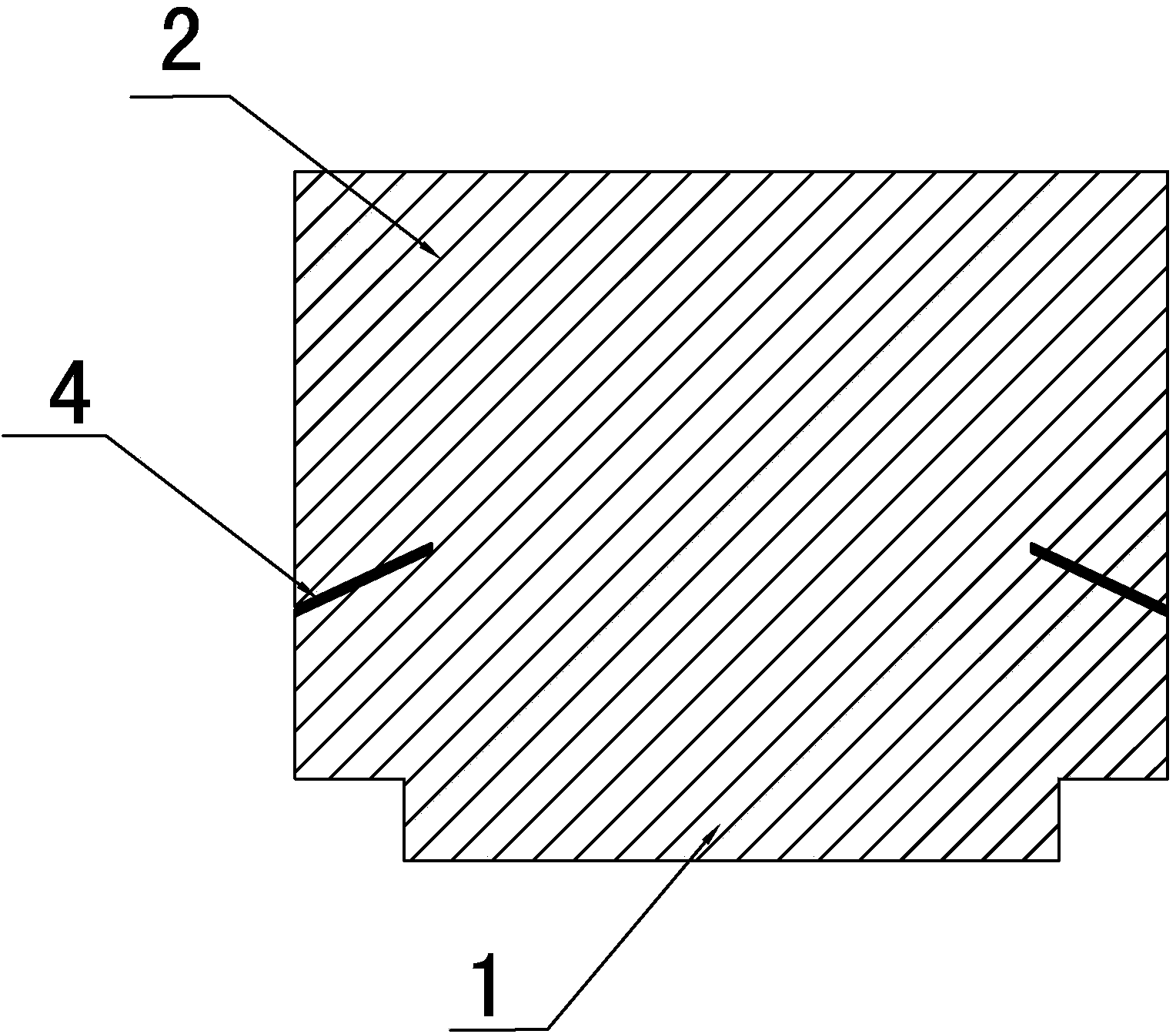
[0018] Embodiment: As shown in the figure, an LED heat sink includes a heat dissipation substrate 1 and a heat dissipation fin group 2. The heat dissipation fin group 2 includes a plurality of heat dissipation fins arranged at intervals on the top surface of the heat dissipation substrate 1, and two adjacent heat dissipation fins A heat dissipation channel 3 is formed between the fins, and the heat dissipation fins are parallel to the closed end of the heat dissipation substrate 1. One end of the plurality of heat dissipation fins on the same side extends out of the edge of the heat dissipation substrate 1. When the heat is transferred to the heat dissipation channel 3, the heat dissipation After the air in the channel 3 absorbs heat, its density decreases and rises to leave the heat dissipation channel 3, and the air with a lower temperature below the heat dissipation channel 3 outside the heat dissipation base 1 enters the heat dissipation channel 3, and it goes round and roun...


PUM


Abstract

The invention discloses an LED radiator comprising a radiating substrate and a radiating fin group. The radiating fin group is composed of a plurality of radiating fins arranged on the top surface of the radiating substrate at intervals, a radiating channel is formed between every two neighboring radiating fins, the radiating fins are parallel to the end portion, used for sealing, of the radiating substrate, and one end, located on the same side, of each radiating fin, extends out of the edge of the radiating substrate. When heat is transmitted to the radiating channels, air, after absorbing the heat, inside the radiating channels is reduced in density and rises prior to flowing out of the radiating channels, and air lower in temperature and located under the radiating channels outside the radiating substrate flows into the radiating channels in circles. The LED radiator has the advantages that the radiating channels communicated from bottom to top allow the air nearby the radiating fins to circulate, so that radiating effect is improved; meanwhile as the radiating channels of the radiator are communicated with the outside, automatic cleaning effect of the radiator can be achieved through rain wash, and stacking of dust and sundries is avoided.

Description

technical field [0001] The invention relates to a radiator, in particular to an LED radiator. Background technique [0002] Existing LED lamps generally include LED light sources, heat transfer fins, and radiators. LED light sources, heat transfer fins, and radiators are arranged in sequence from bottom to top. A plurality of heat sink groups are formed, and the multiple heat sink groups are arranged on the top surface of the heat dissipation substrate. The heat sinks are distributed in a linear array and do not exceed the range of the heat dissipation substrate. A heat dissipation channel is formed between two adjacent heat sinks. The heat dissipation channels on the same straight line are connected to each other, and the installation direction of the heat sink is parallel to the length direction of the heat dissipation substrate. When installing LED lamps, the two ends of the heat dissipation substrate in the width direction are generally provided with partitions. The coo...

Claims


Application Information

Patent Timeline
Patent Type & Authority Applications(China)
IPC IPC(8): F21V29/00F21Y101/02F21V29/76
Inventor 陈云芽
Owner 爱博特电子(宁波)集团有限公司
Why Eureka
Try Eureka