Testing system for fatigue crack propagation test under high/low temperature environment

A technology of fatigue crack growth and low-temperature environment, which is applied in the direction of applying repeated force/pulsation force to test the strength of materials, etc. It can solve the problems of low precision, lack of crack growth performance test system, and difficult fatigue crack growth performance test. Convenience and high measurement accuracy

Inactive Publication Date: 2013-12-18
BEIHANG UNIV
View PDF7 Cites 21 Cited by
  • Summary
  • Abstract
  • Description
  • Claims
  • Application Information

AI Technical Summary

Problems solved by technology

At present, the test of crack growth performance at home and abroad mainly relies on manual observation and recording through magnifying glass marking, which has low precision and is difficult to be used for fatigue crack grow

Method used


Image

  • Testing system for fatigue crack propagation test under high/low temperature environment
  • Testing system for fatigue crack propagation test under high/low temperature environment
  • Testing system for fatigue crack propagation test under high/low temperature environment

Examples


specific Embodiment approach 1

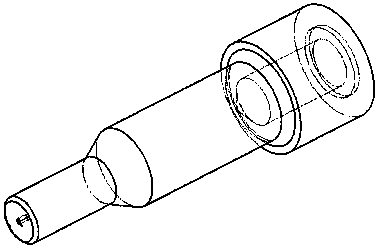
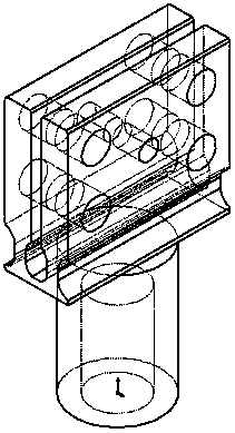
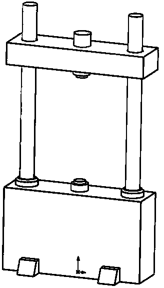
[0024] Specific implementation mode one: combine Figure 1 to Figure 6 Specific embodiments of the present invention will be described. The present invention is a fatigue crack growth test system under high / low temperature environment, which consists of a fatigue testing machine 1, a conversion joint 2, a sample fixture 5, a high / low temperature environment box 3, a liquid nitrogen tank 6, a positioning pin 7, and a crack observation System 8 and sample 4 are composed. exist Image 6 Among them, the sample holder 5 is connected with the sample 4, and the positioning pin 4 passes through the positioning holes of the sample holder 3 and the sample 4 for positioning, which can ensure that the sample 4 is loaded uniformly in the axial direction; The testing machine 5 is connected to the sample fixture 3; the liquid nitrogen tank 6 is connected to the high / low temperature environment box 3; the crack growth process of the sample is monitored and recorded by a three-axis follow-up...

specific Embodiment approach 2

[0026] Embodiment 2: The difference between this embodiment and Embodiment 1 lies in the design of the sample. The sample can be a plate with or without holes in the center, and the dimensional parameters can be different from those in Embodiment 1. , The other design concepts and connection methods of the fatigue crack growth test system under high / low temperature environment are the same as those in the first embodiment.

specific Embodiment approach 3

[0027] Specific embodiment three: the difference between this embodiment and specific embodiment one lies in the design of the sample, the sample can be rod-shaped or other structural forms, and other design ideas and other design concepts of the fatigue crack growth test test system under high / low temperature environment The connection method is the same as that in the first embodiment.


PUM


Abstract

The invention relates to a testing system for a fatigue crack propagation test under a high/low temperature environment. The system comprises a fatigue tester, a conversion joint, a sample fixture, a high/low temperature environmental box, a liquid nitrogen tank, positioning pins, a crack observation system and a sample, wherein the sample fixture is mounted on the fatigue tester through the conversion joint; the sample is connected with the sample fixture and is positioned through the positioning pins passing through the positioning holes of the sample fixture and the sample; the sample fixture and the sample are wrapped in the high/low temperature environmental box; the liquid nitrogen tank and the high/low temperature environmental box are communicated so as to realize the low-temperature environment; the crack observation system is used for recording the propagation of cracks by a computer through a microscope; the fatigue tester, the conversion joint, the sample fixture, the positioning pins and the sample are connected in series. The system provided by the invention is simple in structure and convenient to operate, and is used for testing the fatigue crack propagation property test under the high/low temperature environment. A testing result has an important engineering application value for the tolerance evaluation of structural damages.

Description

technical field [0001] The invention relates to a fatigue crack growth test system under high / low temperature environment, belonging to the technical field of test and test. Background technique [0002] Engineering materials and structures are subjected to alternating loads during use, and fatigue damage may occur. In order to ensure their safety, it is necessary to test their fatigue performance. After years of technological development, a complete fatigue performance testing standard has been formed; however, engineering Materials and structures are also often used in cold or hot environments, therefore, it is necessary to measure their crack growth performance in high / low environments to evaluate their fatigue crack growth life in high / low temperature environments. At present, the test of crack growth performance at home and abroad mainly relies on manual observation and recording through magnifying glass marking, which has low precision and is difficult to be used for f...

Claims


Application Information

Patent Timeline
IPC IPC(8): G01N3/32
Inventor 熊峻江田本鉴陈克姣
Owner BEIHANG UNIV
Why Eureka
Try Eureka