Supercharge Your Innovation With Domain-Expert AI Agents!

Thermoelectric moisture detector

A circuit and thermal energy technology, applied in the application field of chemical accumulators, can solve problems such as the limitation of service life of microsystems, achieve long service life and save costs

Inactive Publication Date: 2013-12-18
ROBERT BOSCH GMBH
View PDF5 Cites 1 Cited by
  • Summary
  • Abstract
  • Description
  • Claims
  • Application Information

AI Technical Summary

Problems solved by technology

The lifetime of the microsystem is limited when only batteries are used

Method used


Image

  • Thermoelectric moisture detector
  • Thermoelectric moisture detector
  • Thermoelectric moisture detector

Examples


Embodiment Construction

[0031] In the following description of a preferred exemplary embodiment of the invention, the same or similar reference signs are used for similarly acting elements shown in different figures, so that a repeated description of these elements is omitted.

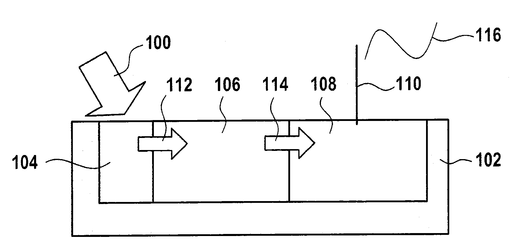
[0032] figure 1 An apparatus for reporting an event 100 according to an embodiment of the invention is shown. The device has a housing 102 , a chemical energy store 104 , a converter 106 and an electrical circuit 108 with an antenna 110 . The housing 102 has a bottom and a surrounding wall. The chemical energy store 104 , the converter 106 and the electrical circuit 108 are arranged within the housing 102 . The housing 102 has no cover. The antenna 110 protrudes from the housing 102 . The chemical energy store 104 , the converter 106 and the circuit 108 are arranged side by side, wherein the converter 106 is arranged between the chemical energy store 104 and the circuit 108 .

[0033] Event 100 , indicated for example by...


PUM


Abstract

The invention relates to a device for reporting events. The device has a chemical energy store (104) which releases thermal energy upon contact with moisture. Furthermore, the device has a converter (106) which is designed so as to convert the thermal energy into electrical energy, and a circuit (108) which is designed to generate an electric signal to report the event when operated by the electrical energy.

Description

technical field [0001] The invention relates to a device for reporting an event, a method for reporting an event, a monitoring system and the use of a chemical energy store which can be used in particular in conjunction with a microsystem. Background technique [0002] Various automated microsystems have been developed. Here, however, the problem of a sufficient energy supply arises, for which a battery or a combination of an energy harvester and a backup battery is used. When using only batteries, the service life of the microsystem is limited. When using energy harvesters, it is basically impossible to guarantee the functionality of the microsystem at a certain moment, because it is not known in advance whether the energy harvester has already obtained enough energy from the environment. The energy harvester is in the form of any energy harvester that harvests energy from the environment. Contents of the invention [0003] Against this background, the use according to...

Claims


Application Information

Patent Timeline
Patent Type & Authority Applications(China)
IPC IPC(8): G01N25/48G01N25/58
CPCG01N25/4873G01N25/56
Inventor F·亨里齐
Owner ROBERT BOSCH GMBH
Features
  • R&D
  • Intellectual Property
  • Life Sciences
  • Materials
  • Tech Scout
  • Unparalleled Data Quality
  • Higher Quality Content
  • 60% Fewer Hallucinations
Learn More