
Method and apparatus for adapting commutation for an electronically commutated electrical machine

An electronic commutation and stator technology, which is applied in the direction of electronic commutator, control using feedback, AC motor control, etc., can solve problems such as imprecise inference of rotor position, inaccuracy, and resolution accuracy of limit position sensors

Active Publication Date: 2013-12-18
ROBERT BOSCH GMBH
View PDF6 Cites 5 Cited by
  • Summary
  • Abstract
  • Description
  • Claims
  • Application Information

AI Technical Summary

Problems solved by technology

However, the adjusting mechanism is often connected to the motor via a reduction gear, so that due to the reduction and due to the unavoidable backlash the rotor position can only be deduced imprecisely
When using an internal position sensor, it may be expedient for cost reasons to limit the accuracy of the resolution of the position sensor
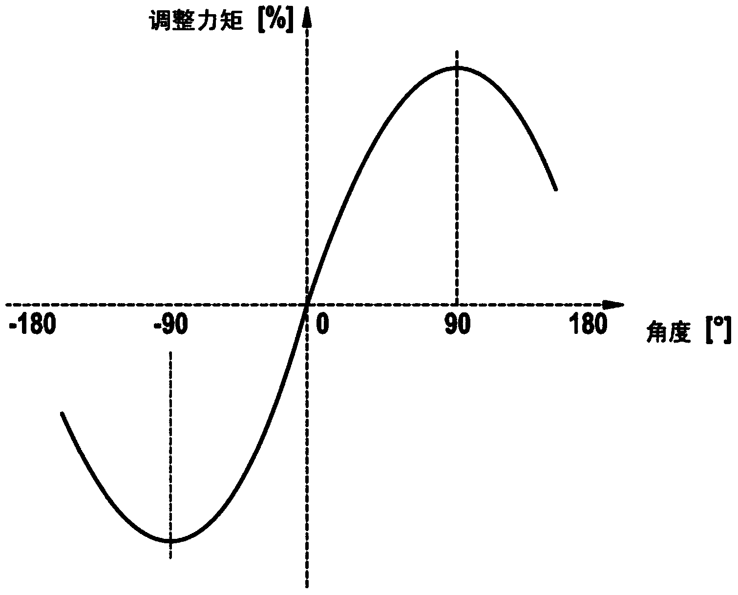
[0007] The inaccuracy when calculating the rotor position from the position of the adjustment mechanism results in the lead not being adjustable to the optimal lead angle of 90°
Therefore, the use of external position sensors for operating electronically commutated motors has the disadvantage that it is not possible to operate the motor with maximum torque

Method used


Image

  • Method and apparatus for adapting commutation for an electronically commutated electrical machine
  • Method and apparatus for adapting commutation for an electronically commutated electrical machine
  • Method and apparatus for adapting commutation for an electronically commutated electrical machine

Examples


Embodiment Construction

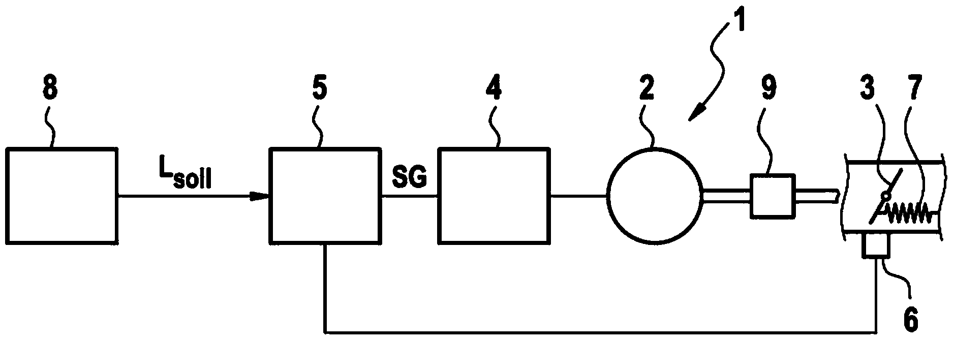
[0042] figure 1 A schematic diagram is shown of a positioner system 1 with a synchronous motor 2 as an electronically commutated motor, wherein the rotor (not shown) of the synchronous motor 2 is coupled to the adjusting mechanism 3 , for example via a transmission 9 or the like. For example, the positioner system can correspond to a throttle regulator in an internal combustion engine, wherein the adjusting mechanism 3 corresponds to the throttle valve. The adjusting mechanism 3 can be acted on by the restoring spring 7 , so that a certain drive torque must be applied by the synchronous motor 2 in order to adjust the adjusting mechanism 3 to a certain position.

[0043] For proper operation, the synchronous motor 2 requires information about the rotor position of the rotor. as in figure 1 As shown in , an external position sensor 6 is provided on the adjustment mechanism 3 . In the exemplary embodiment, the information about the rotor position is ascertained from the positi...


PUM


Abstract

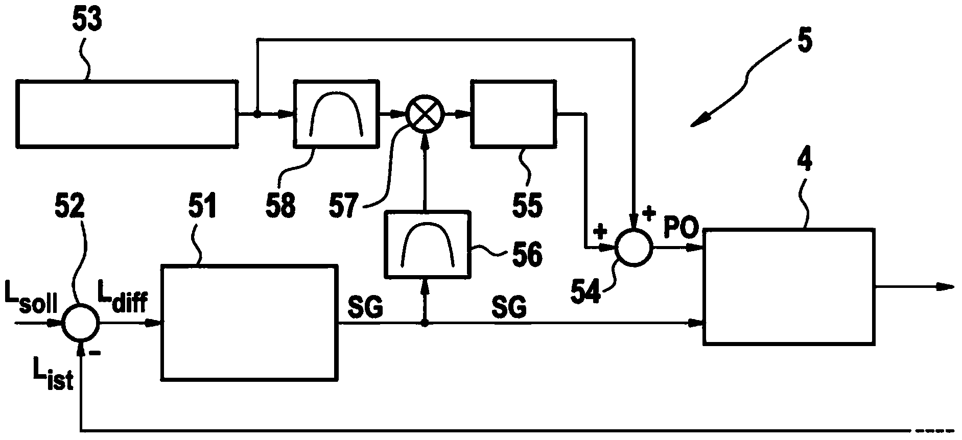
The invention relates to a method for controlling the position of an actuating element (3), to which a restoring force is applied, in an actuator system (1) having an electronically commutated electrical machine (2), comprising the following steps: controlling the position of the actuating element (3) as a function of a predefined setpoint position specification and an actual position specification, wherein the position control means provides an actuating variable (SG) which is associated with a space vector with which a stator arrangement of the electrical machine (2) can be driven; applying a correction variable (PO) to the space vector in order to correct a space vector angle of the space vector; providing an auxiliary signal; varying the space vector angle of the space vector, which is defined by the actuating variable (SG), by the auxiliary signal; integrating a variable to give an integration value, wherein the variable which is to be integrated depends on the auxiliary signal and the actuating variable (SG) of the position control means which was obtained in response to varying the space vector angle of the space vector, wherein the correction variable (PO) is derived from the integration value.

Description

technical field [0001] The present invention generally relates to the control of electronically commutated electric machines, in particular to measures for adapting the lead angle between the excitation field generated at the rotor of the electric machine and the electric motor's magnetic field generated by the commutation of the stator coils. Background technique [0002] Electronically commutated electric machines, such as synchronous or asynchronous electric machines, have a stator and a rotor. The stator is used to provide the motor magnetic field. The rotor includes permanent magnets and / or shorted rotor coils to provide an excitation magnetic field. [0003] The stator has a plurality of stator coils which are each assigned to one or more phases of the electric machine. The stator coils are energized in a suitable manner to operate the electric machine as a motor, thereby generating a motor field. Through the interaction between the motor magnetic field and the exci...

Claims


Application Information

Patent Timeline
Patent Type & Authority Applications(China)
IPC IPC(8): H02P6/16G05D3/12G05D3/20H02P23/00
CPCH02P23/18H02P21/50
Inventor A·格罗斯曼U·西贝尔R·比勒Z·托松
Owner ROBERT BOSCH GMBH
Learn More