Slide block structure of wheel rim slag scraper

A technology of slag scraper and slider, which is applied in the direction of auxiliary devices, auxiliary welding equipment, welding/cutting auxiliary equipment, etc., can solve the problem of slider damage to molds, etc., and achieve the effect of reasonable force

Inactive Publication Date: 2013-12-25
徐州新赛特石英材料有限公司
View PDF0 Cites 0 Cited by
  • Summary
  • Abstract
  • Description
  • Claims
  • Application Information

AI Technical Summary

Problems solved by technology

[0003] The purpose of the present invention is to: aim at the above-mentioned defects in the structure of the slider of the existing wheel rim scraper, and the defects that easily cause the slider and damage the mold. improved technology

Method used


Image

  • Slide block structure of wheel rim slag scraper

Examples


Embodiment Construction

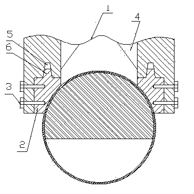
[0010] In the figure, the structure of the slider of the wheel rim slag scraper includes a slider 1, a mold body 2, a positioning bolt 3, a "herringbone"-shaped rib 4, a tapered hole 5, a tapered platform 6, and a right-angle seam 7, A "herringbone"-shaped reinforcing rib 4 is symmetrically arranged on the upper part of the middle opening of the slider 1, and a right-angle stop 7 is symmetrically formed on the openings on both sides of the lower part of the slider 1, and on the horizontal side of the right-angle stop 7 A tapered hole 5 is formed, and the mold body 2 is fixed on the right-angle seam of the slider 1 through a positioning bolt 3, and a conical platform 6 is formed on the upper plane of the mold body 2, and the conical platform 6 is engaged in the Inside the tapered hole 5.


PUM


Abstract

The invention discloses a slide block structure of a wheel rim slag scraper. The upper part of the opening of the middle part of the slide block is symmetrically provided with inverted Y-shaped reinforcing ribs, the opening parts of the two sides of the lower part of the slide block are symmetrically provided with right-angle spigots, the horizontal edge of each right-angle spigot is provided with a conical hole, a die body is fixedly arranged on each right-angle spigot of the slide block through a positioning bolt, the upper plane of each die body is provided with a conical boss, and each conical boss is clamped in the corresponding conical hole. The slide block structure has the advantages that the stress condition of the slide block is more reasonable, and the defect of damage to the slide block and the die due to the unreasonable stress condition in the original slide block is effectively overcome.

Description

technical field [0001] The invention relates to the structure of a slider of a wheel rim slag scraper, and belongs to the technical field of wheel rim slag scrapers. Background technique [0002] The wheel rim slag scraper is mainly used for the post-cleaning of the wheel rim welds of various automobiles. It scrapes off the welding slag and excess metal from the inner and outer welds of the rim to ensure that the welds are smooth and clean. The existing slag scraper slider It is a door-type structure, which is fixed in the "T" groove at the bottom of the slider with bolts. Since the slider is in the process of pressing down, the opening position of the slider has a tendency to expand outwards under the condition of external force. Therefore, the existing slider structure does not have the ability to bear such force, and under the influence of the force in a long-time working state, the slider and the mold installed on the slider are easily damaged. Contents of the inventio...

Claims


Application Information

Patent Timeline
Patent Type & Authority Applications(China)
IPC IPC(8): B23K37/08
Inventor 王永江
Owner 徐州新赛特石英材料有限公司
Why Eureka
Try Eureka