Connection joint between concrete filled steel tube column and reinforced concrete beam and its construction method

A technology for reinforced concrete beams and CFST columns is applied to the connection nodes of CFST columns and reinforced concrete beams and their construction fields, and can solve the problems of reducing the binding force of the tubular core concrete and weakening the steel tube section.

Active Publication Date: 2018-11-02
SHENZHEN GENERAL INST OF ARCHITECTURAL DESIGN & RES
View PDF2 Cites 0 Cited by
  • Summary
  • Abstract
  • Description
  • Claims
  • Application Information

AI Technical Summary

Problems solved by technology

Using the method of opening large holes for reinforcement will weaken the section of the steel pipe to a certain extent, reducing the binding force of the steel pipe to the core concrete

Method used


Image

  • Connection joint between concrete filled steel tube column and reinforced concrete beam and its construction method
  • Connection joint between concrete filled steel tube column and reinforced concrete beam and its construction method
  • Connection joint between concrete filled steel tube column and reinforced concrete beam and its construction method

Examples


Embodiment 1

[0085] This embodiment provides a connection node between a steel tube concrete column and a reinforced concrete beam, which is characterized in that: at the intersection of the steel tube concrete column and the reinforced concrete beam, the steel tube of the steel tube concrete column is provided with a plurality of first openings, The outer peripheral surface of the steel pipe is provided with a reinforcing plate corresponding to the position of the opening, and the reinforcing plate is provided with a second opening overlapping with each of the openings, and the reinforced concrete beam is provided with a A plurality of steel bars corresponding to the first opening, and each steel bar of the reinforced concrete beam respectively passes through the first opening and the second opening at corresponding positions.

Embodiment 2

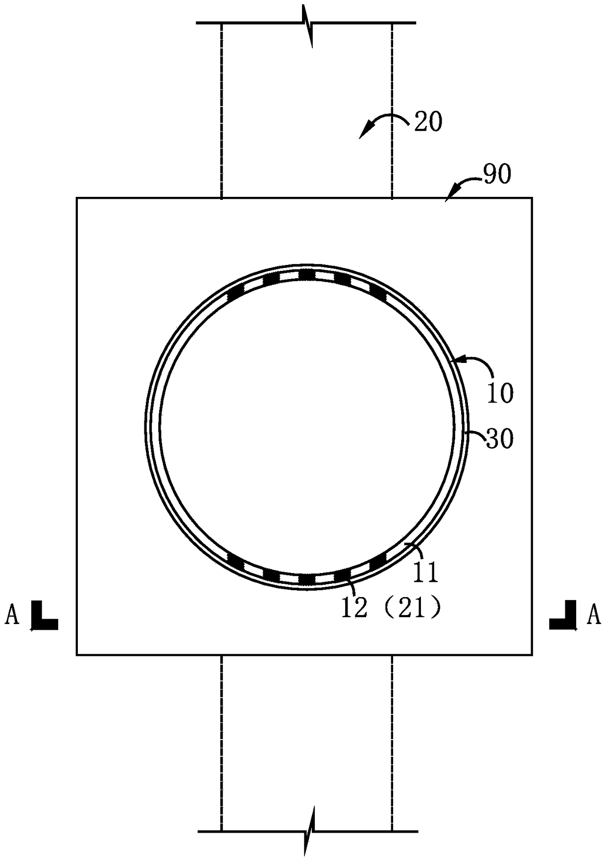
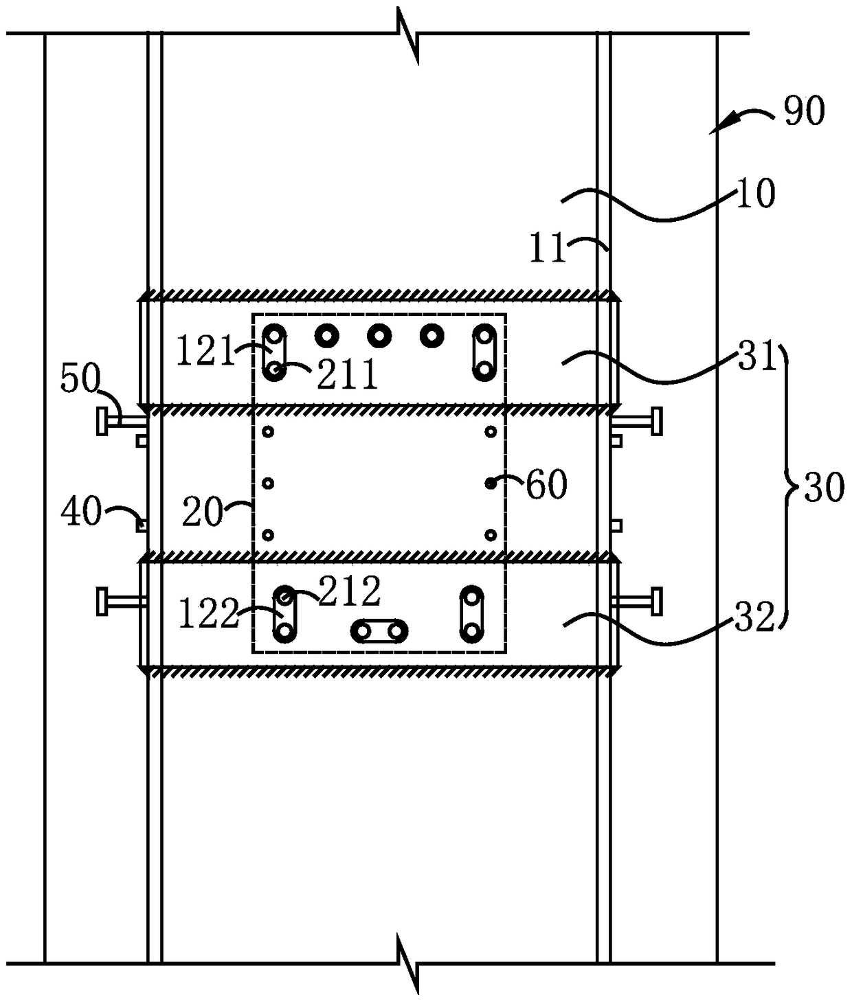
[0087] This embodiment provides a connection node between a steel tube concrete column and a reinforced concrete beam, as shown in FIG. The steel pipe 11 of the CFST column is provided with a plurality of first openings 12, and a reinforcing plate 30 is provided on the outer peripheral surface of the steel pipe 11 corresponding to the position of the first opening, and the reinforcing plate 30 is respectively provided with each first opening. The hole 12 is the second overlapping hole, and the steel bars 21 of the reinforced concrete beam respectively pass through the first hole 12 and the second opening at corresponding positions, so that the CFST column 10 and the reinforced concrete beam 20 intersect to form a connection node. Specifically, such as figure 2 As shown, at the intersection of the steel pipe concrete column 10 and the reinforced concrete beam 20, the first opening 12 includes a first group of openings 121 and a second group of openings respectively provided by...

Embodiment 3

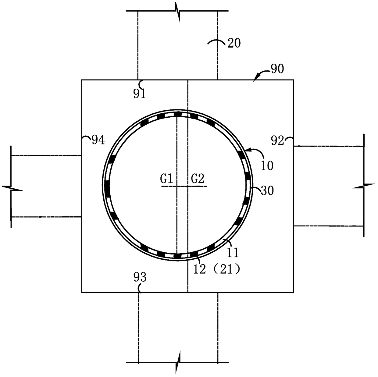
[0098] The difference between this embodiment and the second embodiment lies in that the concrete-filled steel tube column and the composite column in this embodiment are arranged eccentrically. like image 3As shown, the four sides of the composite column 90 are the upper side 91, the right side 92, the lower side 93 and the left side 94 respectively, and the center G1 of the steel pipe 11 of the steel tube concrete column (ie, the center of gravity of the steel tube concrete column) The distances to the upper side 91, the right side 92, the lower side 93 and the left side 94 of the composite column are 800mm, 850mm, 800mm and 750mm in sequence, and the center G1 of the steel tube concrete column is located on the left side of the center G2 of the composite column side.

[0099] In addition, in this embodiment, the CFST columns 10 are respectively aligned with the north-south direction (ie image 3 Reinforced concrete beams extending along the east-west direction (ie ima...


PUM

PropertyMeasurementUnit
diameteraaaaaaaaaa
diameteraaaaaaaaaa
diameteraaaaaaaaaa

Abstract

The invention relates to a connecting node of a concrete filled steel tubular column and a reinforced concrete beam and a construction method of the connecting node. The connecting node is arranged at the junction of the concrete filled steel tubular column and the reinforced concrete beam; a plurality of first holes are formed in the steel tube of the concrete filled steel tubular column; reinforcing plates are arranged on the outer peripheral surface of the steel tube and correspond to the holes; second holes overlapped with the holes are formed in the reinforcing plate; a plurality of reinforced steel bars corresponding to the first holes are respectively arranged in the reinforced concrete beam; the reinforced steel bars of the reinforced concrete beam respectively penetrate through the first holes and the second holes in corresponding positions. By adopting the connecting node of the structure, as the holes in the steel tube are relatively small, the cross section of the steel tube is not greatly weakened, and seams left after the reinforced steel bars penetrate through the small holes are also relatively small, the constraining force of the steel tube to the concrete filled steel tubular column is barely reduced, the bearing capacity and the deformation property of the concrete filled steel tubular column are not affected, and the bearing capacity of the concrete filled steel tubular column is barely affected.

Description

technical field [0001] The invention relates to a beam-column joint construction technology in a building structure, in particular to a joint joint between a steel pipe concrete column and a reinforced concrete beam and a construction method thereof. Background technique [0002] In the existing building structure design, usually the frame columns are steel pipe concrete columns, and the frame beams are ordinary reinforced concrete beams. At the connection node between the CFST column and the reinforced concrete beam, since the beam reinforcement cannot pass directly through the steel pipe, the construction at this node is difficult. Therefore, the joint design of the CFST column and the reinforced concrete beam has become one of the difficulties in engineering design . At present, the commonly used methods for this kind of joints include steel corbel method, double beam method, ring beam method, reinforcement method after opening large holes in steel pipes or pure reinforc...

Claims


Application Information

Patent Timeline
Patent Type & Authority Patents(China)
IPC IPC(8): E04B1/58
CPCE04B1/58E04B2001/5875
Inventor 梁艳王启文李晖陈涛
Owner SHENZHEN GENERAL INST OF ARCHITECTURAL DESIGN & RES
Why Eureka
Try Eureka