
Braiding device

A wire-bundling and ring-shaped technology, which is applied in the field of braiding devices for carding and pulling wires, can solve the problems of the radially outward rebound component force of the pulling wires, the breaking of the pulling wires, and the prolapse of the pulling wires, so as to achieve reasonable stress and improve safety. , ingeniously designed effects

Active Publication Date: 2021-12-10
CHINA RAILWAY MAJOR BRIDGE ENG GRP CO LTD +1
View PDF12 Cites 0 Cited by
  • Summary
  • Abstract
  • Description
  • Claims
  • Application Information

AI Technical Summary

Problems solved by technology

[0006] 1. When the pulling force on the pull wire fluctuates greatly, the pull wire in the groove may come out of the groove. For example, when the heavy object suspended by the pull wire suddenly breaks away from the pull wire, the pull wire will have a large rebound force , which will cause a large radially outward rebound force component of the pull wire near the disc, which may cause the pull wire to come out of the groove
[0007] 2. At the moment when the stay wire lifts the heavy object, the radial inward component force of the stay wire near the disc-shaped body suddenly increases, which in turn causes a large impact between the stay wire and the disc-shaped body. If this impact occurs frequently, it may cause The pull wire breaks at the position of the disc

Method used


Image

  • Braiding device
  • Braiding device
  • Braiding device

Examples


Embodiment Construction

[0049] Unless otherwise defined, the technical terms or scientific terms used in the present invention shall have the usual meanings understood by those skilled in the art to which the present invention belongs. "First", "second" and similar words used in the present invention do not indicate any order, quantity or importance, but are only used to distinguish different components. "Comprising" or "comprising" and similar words mean that the elements or items appearing before the word include the elements or items listed after the word and their equivalents, without excluding other elements or items. Words such as "connected" or "connected" are not limited to physical or mechanical connections, but may include electrical connections, whether direct or indirect. "Up", "Down", "Left", "Right" and so on are only used to indicate the relative positional relationship. When the absolute position of the described object changes, the relative positional relationship may also change acc...


PUM


Abstract

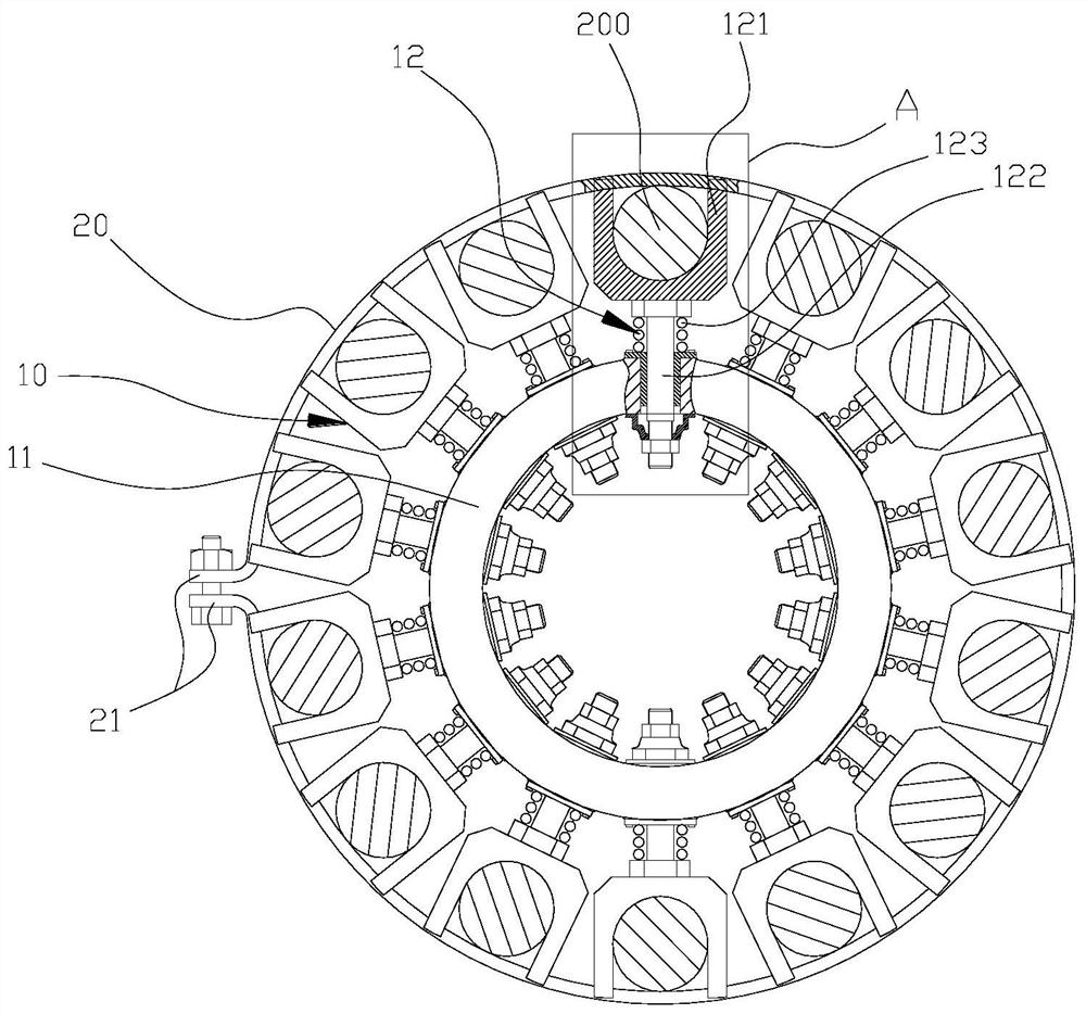
The invention discloses a beam braiding device. The beam braiding device comprises: a beam wire body having circumferentially arranged grooves on it, and the slots of the grooves face radially outward; Covering the outside of the wire harness body, it is used to limit the pulling wire located in the groove to escape from the groove radially outward. By coating the hoop outside the wire harness body, it is possible to effectively prevent the pull wire from detaching from the wire harness body due to tension fluctuations, thereby improving the safety of the wire harness use.

Description

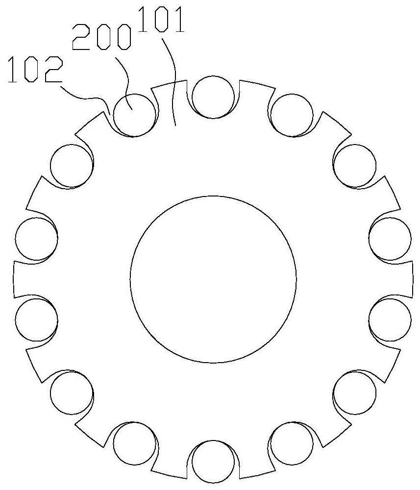
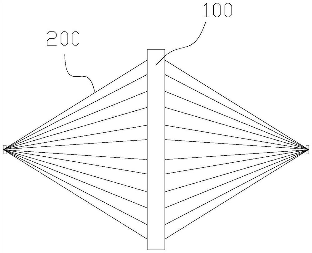
technical field [0001] The invention relates to a braiding device for carding and pulling wires. Background technique [0002] The braiding device (or wire harness) is used to arrange the plurality of pull wires in a circumferential direction, so that the pull wires can obtain a better tensile effect. [0003] Braiding devices are commonly used to sequence longer lengths (or spans) of guy wires, either for static force application (those used to hang heavy loads) or for dynamic force application (Guylines for lifting heavy objects). [0004] Such as figure 1 and figure 2 As shown, the braiding device 100 in the prior art generally includes a disk-shaped body 101, and a plurality of open grooves 102 are opened on the outer periphery of the disk-shaped body 101, and the plurality of grooves 102 are arranged circumferentially, and many Each pull wire 200 is located in a plurality of said grooves 102 in one-to-one correspondence, and all the pull wires 200 are bound togethe...

Claims


Application Information

Patent Timeline
Patent Type & Authority Patents(China)
IPC IPC(8): F16G11/00F16G11/06B66C1/12
CPCF16G11/00F16G11/06B66C1/12
Inventor 张付军陈维李鹏赵伟平倾涛李宁王蔚王凯
Owner CHINA RAILWAY MAJOR BRIDGE ENG GRP CO LTD
Learn More