Three-jaw puller

A three-jaw puller and claw technology, which is applied in the direction of hand-held tools and manufacturing tools, can solve the problem that it is difficult to disassemble objects of various sizes

Inactive Publication Date: 2013-12-25
张家港优尼克五金工具有限公司
View PDF8 Cites 7 Cited by
  • Summary
  • Abstract
  • Description
  • Claims
  • Application Information

AI Technical Summary

Problems solved by technology

Existing three-jaw pullers are difficult to apply to the removal of objects of various sizes

Method used


Image

  • Three-jaw puller

Examples


Embodiment Construction

[0015] Specific embodiments of the present invention will be described in detail below in conjunction with the accompanying drawings.

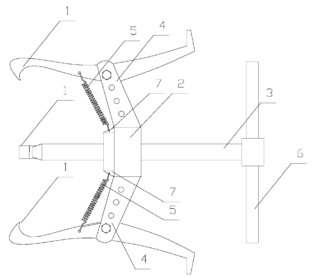
[0016] Such as figure 1 As shown, a three-jaw puller includes three pullers 1, a puller seat 2, and a screw rod 3. The puller 1 is movably arranged on the puller seat 2, and one end of the puller 1 is provided with an inwardly bent puller hook. The puller seat 2 and the screw rod 3 are connected by threads, and the puller seat 2 is evenly distributed with three mounting frames 3 in the circumferential direction. The mounting frame 3 is provided with a number of mounting holes, and the pull claw 1 is arranged on the in the mounting hole. A spring 5 is arranged between the puller seat 2 and the pulling claw 1 . The tail end of the screw 3 is pierced with a force applying rod 6 . The other end of the pull claw 1 is provided with an outward pull hook. The pull claw 1 is provided with a spring installation hole, and the puller seat 2 is evenly ...


PUM


Abstract

The invention discloses a three-jaw puller which comprises three pull jaws, a puller seat and a lead screw. The pull jaws are movably arranged on the puller seat, a pull hook which is bent inwardly is arranged at one end of each pull jaw, the puller seat is connected with the lead screw in a threaded manner, three mounting frames are peripherally uniformly distributed on the puller seat, a plurality of mounting holes are formed in each mounting frame, and the pull jaws are arranged in the mounting holes via bolts and nuts. The three-jaw puller has the advantage that the three-jaw puller is applicable to detaching articles such as bearings with various sizes.

Description

technical field [0001] The invention relates to the field of hardware tools, in particular to a three-jaw puller. Background technique [0002] Three-jaw puller is mainly used to remove damaged bearings, couplings, etc. from the shaft along the axial direction. It is difficult for the existing three-jaw puller to be suitable for disassembling objects of various sizes. Contents of the invention [0003] The technical problem to be solved by the present invention is to provide a three-jaw puller that can be used for dismounting bearings and other objects of various sizes. [0004] In order to solve the above technical problems, the technical solution of the present invention is: a three-jaw puller, including three pullers, a puller seat, and a screw rod, the puller is movably arranged on the puller seat, and one end of the puller is provided with an inward The curved hook, the puller seat and the screw rod are connected by threads, and the puller seat is evenly distributed...

Claims


Application Information

Patent Timeline
Patent Type & Authority Applications(China)
IPC IPC(8): B25B27/06
Inventor 李华
Owner 张家港优尼克五金工具有限公司
Why Eureka
Try Eureka