
LNG (liquefied natural gas) high-flow-rate gas release column

A technology of unloading column and large flow, applied in the field of LNG filling, can solve the problems of no LNG unloading column, inconvenient LNG unloading, measurement value error, etc., and achieve accurate filling and unloading measurement, convenient data management, and simple use. handy effect

Active Publication Date: 2013-12-25
HOPE CLEAN ENERGY (GRP) CO LTD
View PDF6 Cites 4 Cited by
  • Summary
  • Abstract
  • Description
  • Claims
  • Application Information

AI Technical Summary

Problems solved by technology

[0002] At present, the liquid filling flow rate of LNG liquid filling machines on the market is in the range of 3-80 kg / min. Such a small working flow rate determines that it is only suitable for LNG The gas filling station performs liquid filling measurement for automobile steel cylinders, while the liquid filling measurement of the LNG parent station for the mobile tanker and the unloading measurement of the mobile tanker for the LNG filling station do not have special large-flow metering equipment to undertake this work. At the same time, there is no special LNG unloading column, which causes many inconveniences in LNG unloading
[0003] In the LNG industry, the current method of moving tankers to unload LNG filling stations is to pass the weighbridge. If there is no weighbridge near the LNG station, the tanker The car has to be driven far away to be weighed, which is very inconvenient, time-consuming and laborious to unload the car, and there are also cases where there are large errors in the measurement value
[0004]The unloading metering data obtained by the traditional method of passing the floor scale is manual data, which cannot be uploaded to the LNG filling station at all, and the filling station cannot perform unified data management

Method used


Image

  • LNG (liquefied natural gas) high-flow-rate gas release column
  • LNG (liquefied natural gas) high-flow-rate gas release column
  • LNG (liquefied natural gas) high-flow-rate gas release column

Examples


Embodiment Construction

[0023] Below in conjunction with accompanying drawing, the present invention is described in detail.

[0024] In order to make the object, technical solution and advantages of the present invention clearer, the present invention will be further described in detail below in conjunction with the accompanying drawings and embodiments. It should be understood that the specific embodiments described here are only used to explain the present invention, not to limit the present invention.

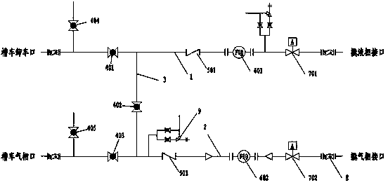
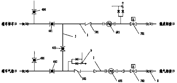
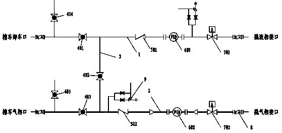
[0025] Such as figure 1 As shown, the LNG large-flow unloading column of the present invention includes a liquid feeding pipeline 1 and a gas return pipeline 2. The two ends of the gas pipeline 2 are the gas phase port of the tank car and the gas phase port of the skid respectively. The two ends of the liquid adding pipeline 1 are respectively provided with metal hoses 8 near the unloading port of the tank car and the liquid phase port of the skid. The two ends of the road 2 are respectively pro...


PUM


Abstract

The invention discloses an LNG (liquefied natural gas) high-flow-rate gas release column, which belongs to the technical field of LNG liquid addition. The LNG high-flow-rate gas release column comprises a liquid adding pipeline and a gas return pipeline, wherein the two ends of the liquid adding pipeline are respectively provided with a tank car unloading opening and a prying equipment liquid phase interface, the two ends of the gas return pipeline are respectively a tank car gas phase opening and a prying equipment gas phase interface, the middle part of the liquid adding pipeline is communicated with the middle part of the gas return pipeline through a pressure regulating pipeline, a first stop valve is arranged between a connecting point of the pressure regulating pipeline and the tank car unloading opening of the liquid adding pipeline, a first mass flow rate meter is arranged between the connecting point of the pressure regulating pipeline of the liquid adding pipeline and the prying equipment liquid phase interface, a second stop valve is arranged between the tank car gas phase interface of the gas return pipeline and the connecting point of the pressure regulating pipeline, a second mass flow rate meter is arranged between the connecting point of the pressure regulating pipeline of the gas return pipeline and the prying equipment gas phase interface, and a second stop valve is arranged on the pressure regulating pipeline. The LNG high-flow-rate gas release column has the advantages that the high-flow-rate requirements can be met, and a tank car can be conveniently and fast moved for realizing the unloading metering.

Description

technical field [0001] The invention relates to the technical field of LNG liquid addition, in particular to an LNG large-flow unloading column. Background technique [0002] At present, the liquid filling flow rate of LNG filling machines on the market is in the range of 3-80 kg / min. Such a small working flow rate determines that it is only suitable for LNG filling stations to fill and measure automobile steel cylinders, while LNG master stations There is no special large-flow metering equipment for the liquid filling metering of the mobile tanker and the unloading metering of the mobile tanker to the LNG filling station. At the same time, there is no special LNG unloading column, resulting in the LNG There are many inconveniences in unloading. [0003] In the LNG industry, the current method of moving tank trucks to unload LNG filling stations is to pass the weighbridge. When there is no weighbridge near the LNG station, the tank truck has to drive far away to weighbridge...

Claims


Application Information

Patent Timeline
Patent Type & Authority Applications(China)
IPC IPC(8): F17D3/01F17D3/18
Inventor 杨国柱魏瑛唐瑜君罗军甘鹏武佳慧江群
Owner HOPE CLEAN ENERGY (GRP) CO LTD
Learn More