A device for static and dynamic multifunctional testing of supports
What is Al technical title?
Al technical title is built by PatSnap Al team. It summarizes the technical point description of the patent document.
A multi-functional testing, static and dynamic technology, applied in the direction of measuring device, testing of mechanical parts, testing of machine/structural parts, etc., can solve the problem of large force on moving beams, increased torque of specimens, lateral side force equipment yaw and other problems, to achieve the effect of meeting the requirements of experimental accuracy, reducing processing, and reducing the risk of leakage
Active Publication Date: 2016-04-13
CCCC HIGHWAY BRIDNAT ENG RES CENT
View PDF6 Cites 0 Cited by
Summary
Abstract
Description
Claims
Application Information
AI Technical Summary
This helps you quickly interpret patents by identifying the three key elements:
Problems solved by technology
Method used
Benefits of technology
Problems solved by technology
However, the existing bearing testing machines in our country cannot fully and systematically meet the testing requirements.
[0005] The domestic support performance test system has the following main difficulties or defects: First, at present, only the static compression shear test of the support can be carried out, and the dynamic loading test cannot be carried out
Second, when the bearing performance testing system itself has low stiffness or the friction force of the lateral bearing mechanism is large, under the action of a large-tonnage servo actuator, the fuselage will be deformed by force or the moving beam will be subjected to a large force, resulting in additional load; In addition, when the horizontal servo actuator performs the shear test, there is a phenomenon that the friction force is too large and affects the test accuracy, causing errors to affect the test results
Third, none of the bearing performance testing systems in China is equipped with an environmental control function, which cannot truly simulate the static and dynamic performance of the bearing under the environmental conditions of the actual project, and it is difficult to guarantee the working performance, durability and safety of the bearing
Fourth, when the vertical large-tonnage actuator moves up and down due to the characteristics of the sealing structure, the guide device and the actuator will rotate, increasing the torque of the specimen; in addition, the lateral force generated when vertical loading is too large Make the equipment deflect and affect the test accuracy
Method used
Image
Click on the blue label to locate the original text in one second.
Reading with bidirectional positioning of images and text.
Examples
Embodiment Construction
[0034] In order to make the object, technical solution and advantages of the present invention clearer, the present invention will be described in further detail below in conjunction with specific embodiments and with reference to the accompanying drawings.
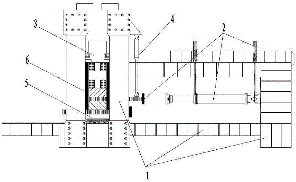
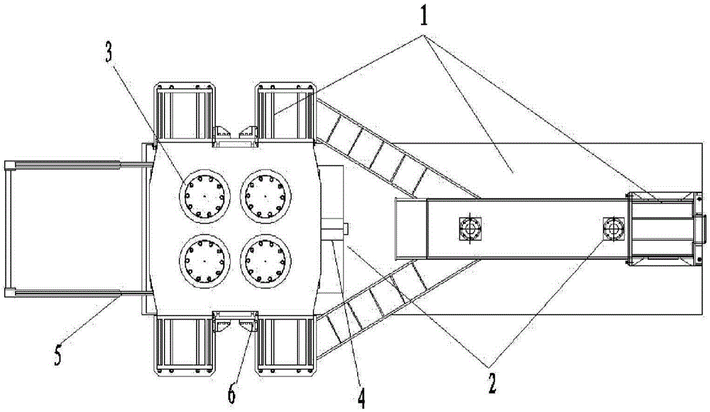
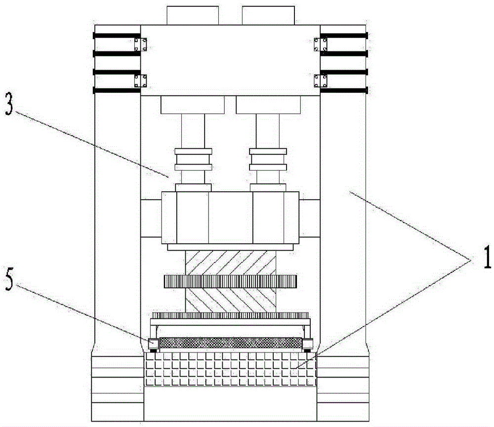
[0035] Such as Figure 1 ~ Figure 3 As shown, the device provided by the present invention for static and dynamic multifunctional testing of supports includes a main machine mechanical part 1, a horizontal shear part 2, a vertical loading part 3, a corner loading part 4, a transport trolley 5, a linear guide rail device 6, Environmental chamber, measurement and control part and hydraulic part. The horizontal shearing part 2, the vertical loading part 3 and the corner loading part 4 are installed on the main machine mechanical part 1 to form the loading body. The horizontal servo actuator 201 is suspended horizontally, hinged with the chute inside the self-balancing column 103 of the main machine mechanical part 1, and pr...
PUM
Abstract
The invention discloses a device for carrying out static-dynamic force multifunction testing on a support. The device comprises a main machine mechanical part, a horizontal shearing part, a vertical loading part, a corner loading part, a conveying trolley, a straight line guiding track device, an environment box, a measurement and control part and a hydraulic part. A horizontal servo actuator of the horizontal shearing part is hung horizontally and is hinged to a sliding groove in the inner side of a self-balancing stand column of the main machine mechanical part, and horizontal loading is provided for the support to be tested. The upper end of a vertical servo actuator of the vertical loading part is fixed on an upper horizontal beam of the main machine mechanical part, the lower end of the vertical servo actuator is connected with a movable horizontal beam, and vertical loading is provided for the support to be tested. The corner loading part is parallel to the vertical loading part and is fixed on the outer side of the upper horizontal beam of the main machine mechanical part, and the corner loading part is used for completing corner testing. The conveying trolley is arranged on a conveying track of the main machine mechanical part, and the straight line guiding track device is arranged on the inner side of a bearing stand column of the main machine mechanical part. The measurement and control part and the hydraulic part are connected with the horizontal shearing part, the vertical loading part and the corner loading part respectively.
Application Information
Patent Timeline
Application Date:The date an application was filed.
Publication Date:The date a patent or application was officially published.
First Publication Date:The earliest publication date of a patent with the same application number.
Issue Date:Publication date of the patent grant document.
PCT Entry Date:The Entry date of PCT National Phase.
Estimated Expiry Date:The statutory expiry date of a patent right according to the Patent Law, and it is the longest term of protection that the patent right can achieve without the termination of the patent right due to other reasons(Term extension factor has been taken into account ).
Invalid Date:Actual expiry date is based on effective date or publication date of legal transaction data of invalid patent.