Device for carrying out static-dynamic force multifunction testing on support

A multi-functional testing, static and dynamic technology, applied in the direction of measuring device, testing of mechanical components, testing of machine/structural components, etc., can solve the problems of large force on the moving beam, increase the torque of the test piece, error, etc., and reduce the processing time. , reduce the risk of leakage, and meet the effect of experimental accuracy requirements

Active Publication Date: 2014-01-15
CCCC HIGHWAY BRIDNAT ENG RES CENT
View PDF6 Cites 13 Cited by
  • Summary
  • Abstract
  • Description
  • Claims
  • Application Information

AI Technical Summary

Problems solved by technology

However, the existing bearing testing machines in our country cannot fully and systematically meet the testing requirements.
[0005] The domestic support performance test system has the following main difficulties or defects: First, at present, only the static compression shear test of the support can be carried out, and the dynamic loading test cannot be carried out
Second, when the bearing performance testing system itself has low stiffness or the friction force of the lateral bearing mechanism is large, under the action of a large-tonnage servo actuator, the fuselage will be deformed by force or the moving beam will be subjected to a large force, resulting in additional load; In addition, when the horizontal servo actuator performs the shear test, there is a phenomenon that t

Method used


Image

  • Device for carrying out static-dynamic force multifunction testing on support
  • Device for carrying out static-dynamic force multifunction testing on support
  • Device for carrying out static-dynamic force multifunction testing on support

Examples


Example Embodiment

[0034] In order to make the objectives, technical solutions and advantages of the present invention clearer, the present invention will be further described in detail below with reference to specific embodiments and accompanying drawings.

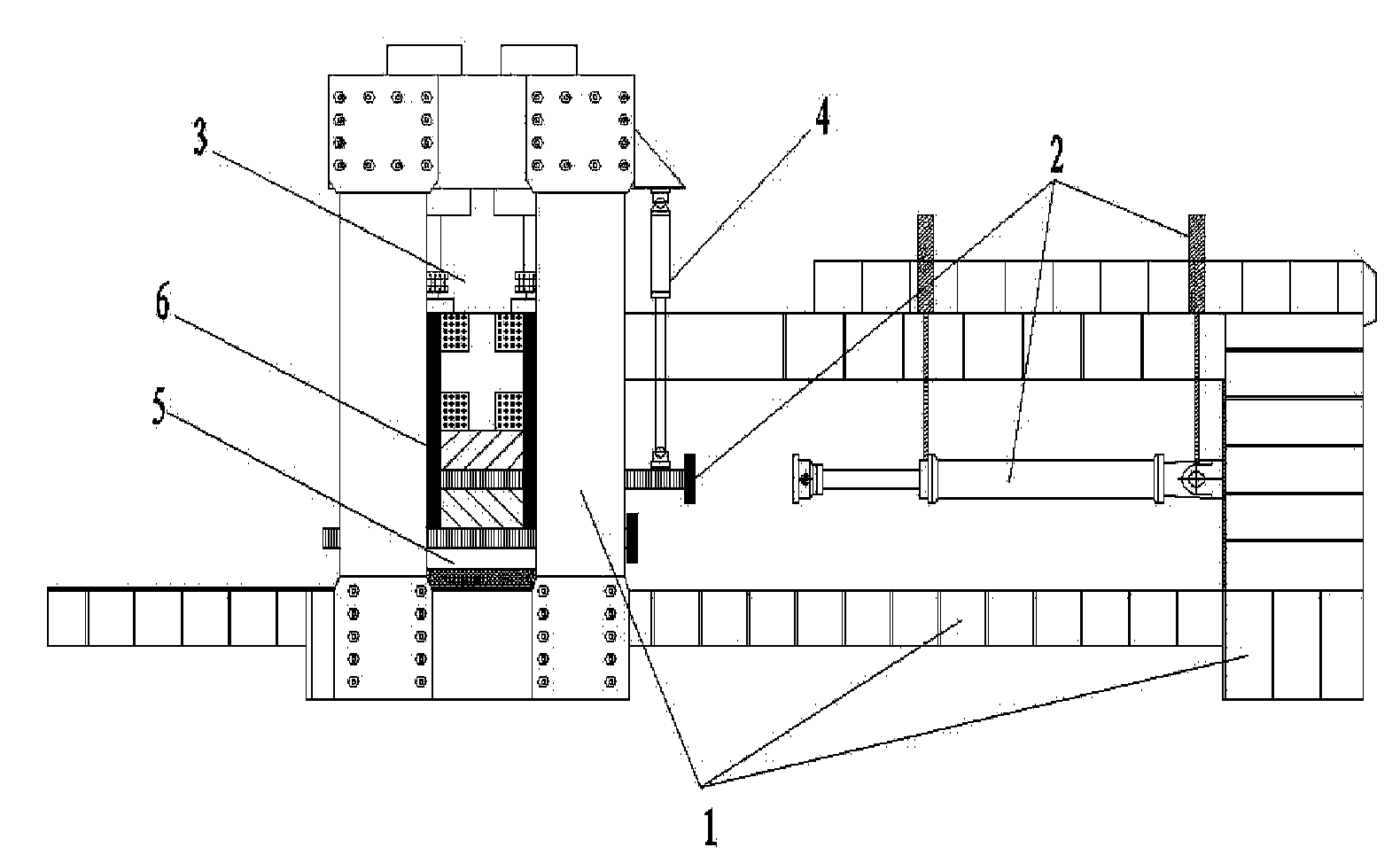
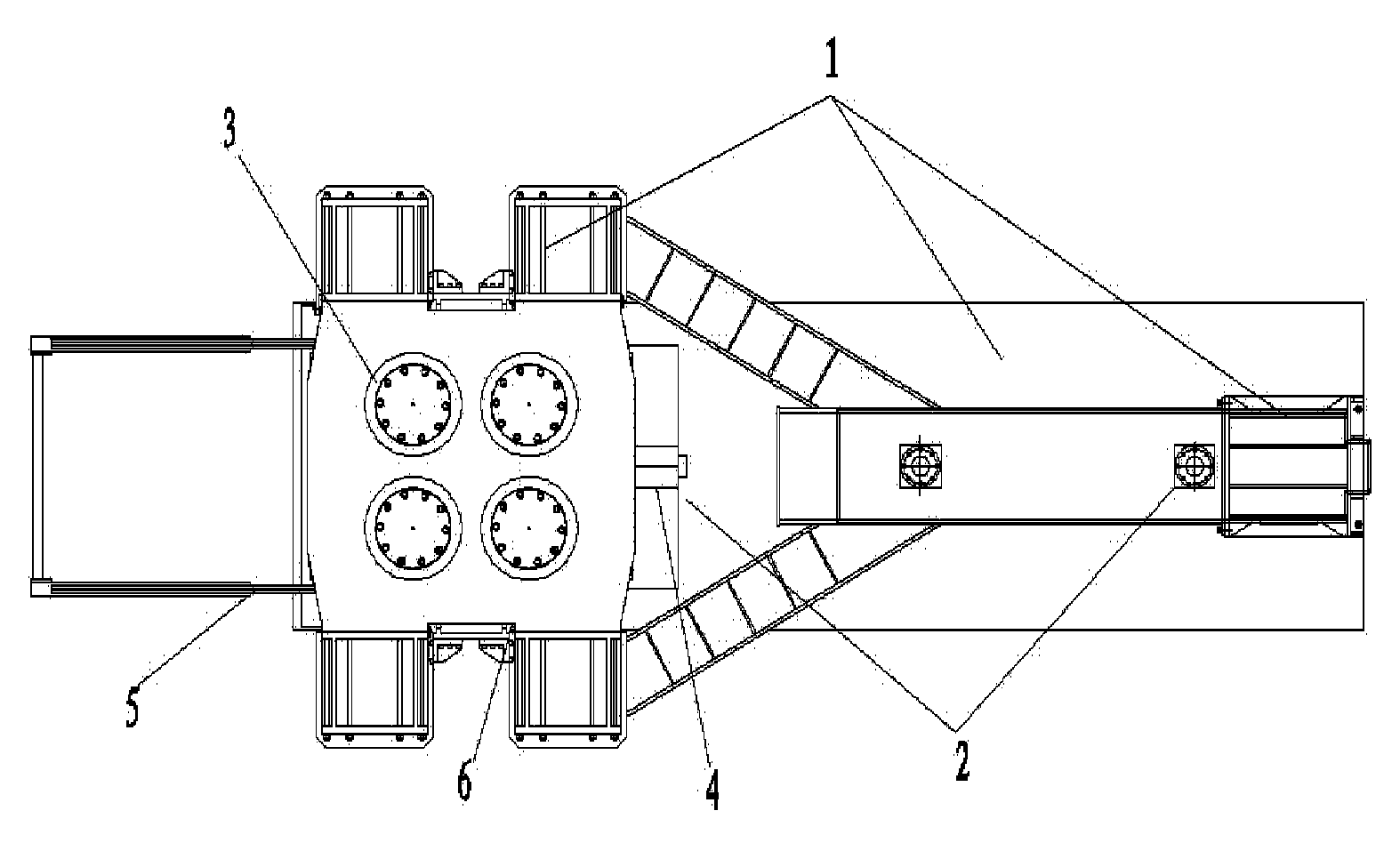
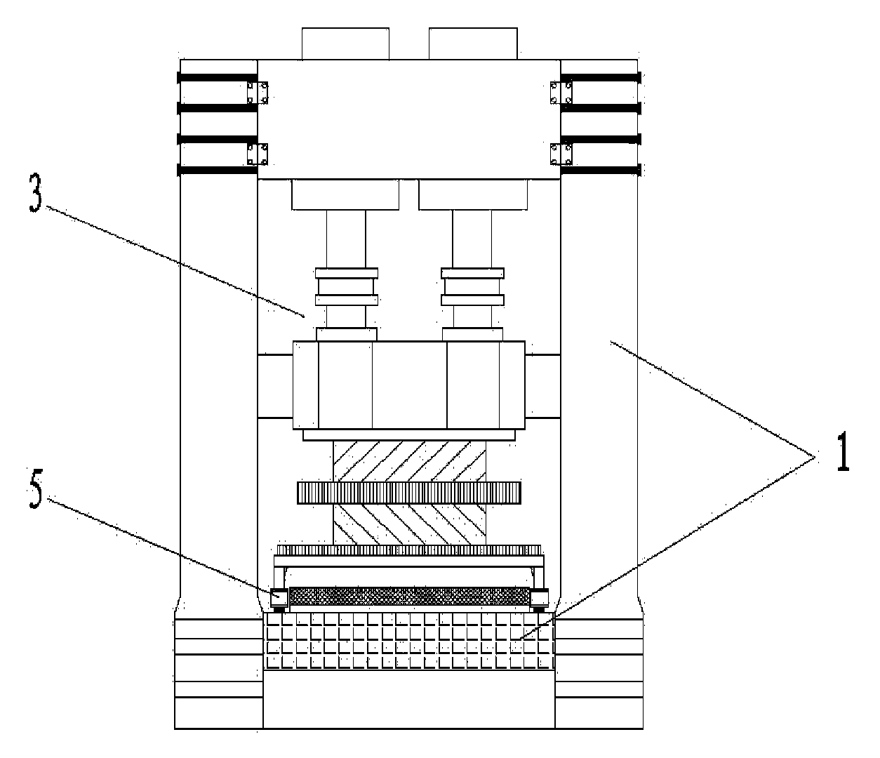
[0035] like Figure 1 to Figure 3 As shown, the device for performing static and dynamic multi-function testing on the support provided by the present invention includes a main machine mechanical part 1, a horizontal shearing part 2, a vertical loading part 3, a corner loading part 4, a transport trolley 5, a linear guide device 6, Environmental box, measurement and control part and hydraulic part. The horizontal shearing part 2, the vertical loading part 3 and the corner loading part 4 are installed on the main machine mechanical part 1 to constitute the loading main body. The horizontal servo actuator 201 is suspended horizontally, and is hinged with the inner chute of the self-balancing column 103 of the main machine part 1 to provide h...


PUM


Abstract

The invention discloses a device for carrying out static-dynamic force multifunction testing on a support. The device comprises a main machine mechanical part, a horizontal shearing part, a vertical loading part, a corner loading part, a conveying trolley, a straight line guiding track device, an environment box, a measurement and control part and a hydraulic part. A horizontal servo actuator of the horizontal shearing part is hung horizontally and is hinged to a sliding groove in the inner side of a self-balancing stand column of the main machine mechanical part, and horizontal loading is provided for the support to be tested. The upper end of a vertical servo actuator of the vertical loading part is fixed on an upper horizontal beam of the main machine mechanical part, the lower end of the vertical servo actuator is connected with a movable horizontal beam, and vertical loading is provided for the support to be tested. The corner loading part is parallel to the vertical loading part and is fixed on the outer side of the upper horizontal beam of the main machine mechanical part, and the corner loading part is used for completing corner testing. The conveying trolley is arranged on a conveying track of the main machine mechanical part, and the straight line guiding track device is arranged on the inner side of a bearing stand column of the main machine mechanical part. The measurement and control part and the hydraulic part are connected with the horizontal shearing part, the vertical loading part and the corner loading part respectively.

Description

technical field [0001] The invention relates to a device for static and dynamic multifunctional testing of bearings, which mainly relates to the mechanical performance testing of shock-absorbing and isolation bearings and ordinary bearings in the construction of highway bridges, railway bridges, building constructions, etc., and can complete compression tests and rotation angle tests. , shear test, shear performance correlation test, friction coefficient test and mechanical tests of some small components, etc. Background technique [0002] In the past two decades, structural protection systems for bridge vibration reduction have developed greatly, and the structural protection systems that have developed rapidly internationally and are widely accepted include liquid viscous dampers, metal friction pendulums, and lead rubber bearings. Wait. Large-scale bridges that have been completed or are under construction in my country have also adopted the design of shock-absorbing and...

Claims


Application Information

Patent Timeline
IPC IPC(8): G01M13/00
Inventor 张喜刚刘高李贞新冯清海徐源庆黄李骥唐亮王毅
Owner CCCC HIGHWAY BRIDNAT ENG RES CENT
Why Eureka
Try Eureka