Serial-parallel centrifugal fan and control method thereof

A centrifugal fan and control method technology, applied in pump control, mechanical equipment, machine/engine, etc., can solve the problems of large size, low external static pressure of the fan machine, complex structure, etc., achieve high product reliability and avoid complex structure , Simple structure and reliable effect

Inactive Publication Date: 2019-06-04
宁波引同工业设计有限公司
View PDF0 Cites 0 Cited by
  • Summary
  • Abstract
  • Description
  • Claims
  • Application Information

AI Technical Summary

Problems solved by technology

[0007] The present invention mainly solves the problems of low external static pressure, large size and complex structure of the existing fan machine, so that the centrifugal fan has the characteristics of large flow rate, high external static pressure and other working modes and small size.

Method used


Image

  • Serial-parallel centrifugal fan and control method thereof
  • Serial-parallel centrifugal fan and control method thereof
  • Serial-parallel centrifugal fan and control method thereof

Examples


Embodiment 1

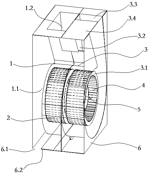
[0036] Such as figure 1 As shown, the series-parallel centrifugal fan provided by the present invention includes a left volute (1), a left centrifugal fan (2), a right volute (3), a right centrifugal fan (4), a motor assembly (5), an outer cover ( 6).

[0037] Such as figure 1 As shown, the left volute (1) of the series-parallel centrifugal fan is provided with a left volute air inlet (1.1) and a left volute air outlet (1.2); the left centrifugal fan (2) is arranged on the left volute (1) Inside; after the air flow enters the centrifugal fan from the left volute air inlet (1.1), it can only flow out of the centrifugal fan from the left volute air outlet (1.2).

[0038] The right volute (3) of the series-parallel centrifugal fan is provided with a right volute air inlet (3.1), a right volute air outlet (3.2), and a second air outlet (3.3); the right centrifugal blade (4) It is arranged inside the right volute (3).

[0039] Further, such as figure 1As shown, the right volut...

Embodiment 2

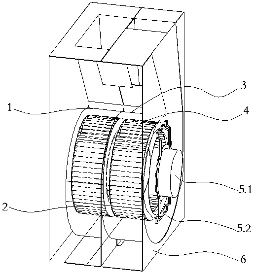
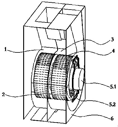
[0050] Such as figure 2 As shown, different from Embodiment 1, in Embodiment 2, the motor assembly (5) of the series-parallel centrifugal fan is arranged on the outer cover (6).

[0051] The motor assembly (5) includes a motor (5.1) and a motor bracket (5.2), the motor (5.1) is fixed on the motor bracket (5.2) by bolts, and the motor bracket (5.2) is installed on the outer cover (6).

[0052] The rotating shaft of the motor (5.1) extends into the inside of the left volute (1) and the right volute (3).

[0053] The left centrifugal fan blade (2) and the right centrifugal fan blade (4) are installed on one end of the motor (5.1) rotating shaft respectively. The other structures and working principles of the centrifugal fan in Embodiment 2 are the same as those in Embodiment 1, and will not be repeated here.

[0054] The invention solves the problems of low external static pressure, large size and complex structure of the fan in the prior art, and makes the centrifugal fan hav...


PUM


Abstract

The invention provides a serial-parallel centrifugal fan and a control method thereof. The serial-parallel centrifugal fan comprises a left volute (1), a left centrifugal fan blade (2), a right volute(3), a right centrifugal fan blade (4), a motor assembly (5) and an outer cover (6). The left volute (1) is provided with a left volute air inlet (1.1) and a left volute air outlet (1.2). The right volute (3) is provided with a right volute air inlet (3.1), a right volute air outlet (3.2), a second air outlet (3.3) and an air outlet control assembly (3.4). The outer cover is provided with an outer cover left air inlet (6.1) and an outer cover left air inlet control assembly (6.2). The opening or closing of the right volute air outlet (3.2) and the second air outlet (3.3) is controlled throughthe air outlet control assembly (3.4), the opening or closing of the outer cover left air inlet (6.1) is controlled through the outer cover left air inlet control assembly (6.2), and the switching operation of the centrifugal fan in three modes of the small air volume high static pressure mode, the large air volume low static pressure mode and the middle air volume middle static pressure mode isrealized through different combinations, so that the requirements of products for different working conditions of the centrifugal fan are met.

Description

technical field [0001] The invention relates to the technical field of ventilators, in particular to a centrifugal ventilator and a control method thereof. Background technique [0002] Centrifugal fans are widely used in home appliances, such as range hoods, air conditioners, and air purifiers. The motor drives the wind wheel to rotate at high speed to obtain kinetic energy for the gas, and realize the conversion from dynamic pressure energy to static pressure energy inside the volute, so as to realize the efficient flow of gas and meet the functional requirements of home appliances. [0003] For products that need to operate in conjunction with the resistance of the external pipe network, it is often hoped that the product can achieve a large flow rate when the external pipe network has a low static pressure, and that the product also has a high external static pressure when the external pipe network has a high static pressure to overcome the resistance of the pipe network...

Claims


Application Information

Patent Timeline
Patent Type & Authority Applications(China)
IPC IPC(8): F04D25/08F04D25/16F04D29/42F04D27/00F04D29/66
Inventor 张甜甜张莉
Owner 宁波引同工业设计有限公司
Why Eureka
Try Eureka