Plunger pump transmission device

A technology of transmission device and plunger pump, which is applied in the direction of transmission device, components of pumping device for elastic fluid, pump, etc. The effect of large lateral force, reduced axial size, and reduced equipment volume

Inactive Publication Date: 2017-11-07
殷图源
View PDF10 Cites 0 Cited by
  • Summary
  • Abstract
  • Description
  • Claims
  • Application Information

AI Technical Summary

Problems solved by technology

However, the constant flow pump with this structure is not suitable for long-term constant flow occasions. Long-term operation is likely to cause wear of the cam pair and fatigue of the spring.
At the same time, due to the pressure angle of the cam drive, it will also cause lateral wear and loss of feeding accuracy, which will cause a series of problems such as blockage of thinner pipelines.
[0004] In the large flow area: due to the increase in load, the plunger pump of the cam drive device is a high-speed secondary drive formed by the direct contact between the cam and the plunger wheel rod. The contact stress limits the application range and is not su

Method used


Image

  • Plunger pump transmission device
  • Plunger pump transmission device
  • Plunger pump transmission device

Examples


Example Embodiment

[0028] The principles and features of the present invention will be described below with reference to the accompanying drawings. The examples are only used to explain the present invention, but not to limit the scope of the present invention.
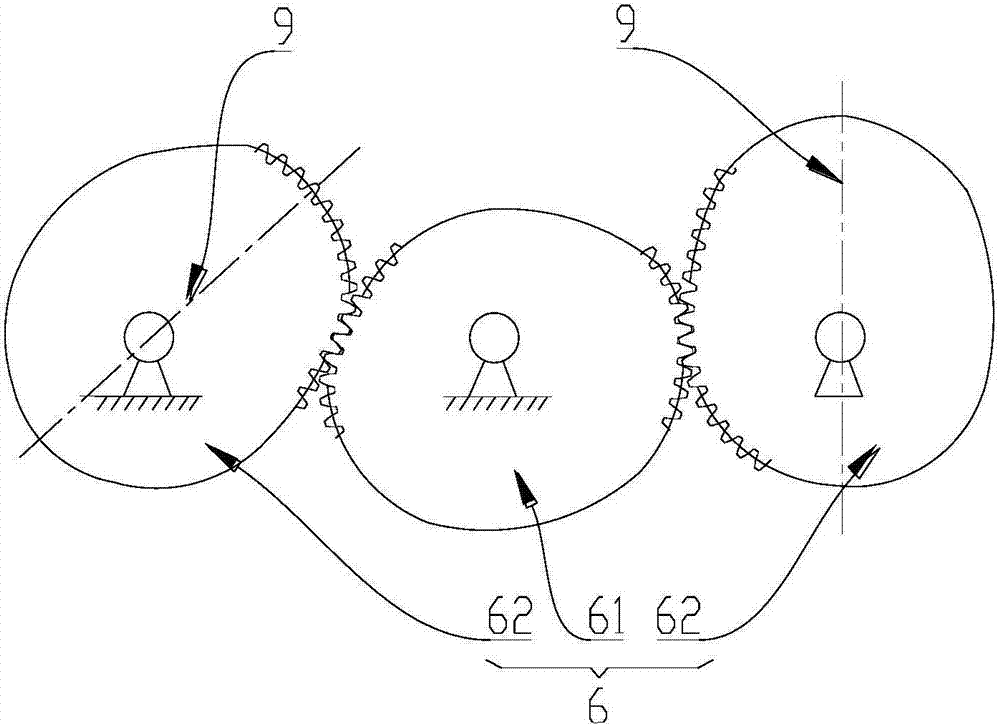
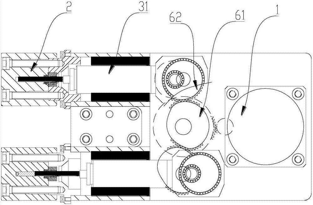
[0029] like Figure 1 to Figure 6 shown, figure 1 A schematic cross-sectional view of a specific embodiment of a plunger pump transmission device provided by the present invention; figure 2 for figure 1 Schematic diagram of the three-dimensional structure of the specific embodiment shown; image 3 for figure 1 an exploded view of the embodiment shown; Figure 4 Schematic diagram of the assembly of the power actuator assembly 3; Figure 5 is a schematic structural diagram of the power transmission assembly 6; Image 6 for figure 1 A schematic diagram of the pipeline connection of the pump body 2 in the illustrated embodiment.

[0030] In a specific embodiment of a plunger pump transmission device provided by the present inventio...


PUM


Abstract

The invention relates to a plunger pump transmission device. The plunger pump transmission device comprises a driving device and pump bodies, and further comprises power executing assemblies, wherein the power executing assemblies comprise guide rod shafts which move in the pump bodies in a reciprocating mode, eccentric discs and eccentric shafts; round swinging holes are formed in the ends, extending the pump bodies, of the guide rod shafts; the eccentric discs are round, the eccentric discs are arranged in the swinging holes and are rotationally connected with the swinging holes, round eccentric holes are formed in the eccentric discs, and the rotation axes of the eccentric holes are parallel to the rotation axes of the eccentric discs; and the eccentric shafts comprise power output ends and power input ends, the power output ends are arranged in the eccentric holes and are rotationally connected with the eccentric holes, and the power input ends are connected with the driving device. The plunger pump transmission device cannot only be applied to a small-flow region for a long time, but also can be applied to a large-flow area; and the plunger pump transmission device is long in service life, compact in structure and small in size.

Description

technical field [0001] The invention relates to a liquid power delivery device, in particular to a plunger pump transmission device. Background technique [0002] In recent years, the preparative chromatography industry and the supercritical industry have developed rapidly. The development needs of the traditional petrochemical industry, especially the high-pressure fracturing pumps in shale oil fields, require high-pressure plunger pumps with large flow and non-pulsating transport of chemical media, with a pressure range of 5MPa to 100MPa. The flow range is divided into two levels: small flow area laboratory type, 0.01~500mL / min; large flow industrial manufacturing type, 0.5~50L / min. The transmission medium is water, methanol, acetone, propylene, butane, liquid carbon dioxide, etc. Generally, no pulse transmission is required for system stability. [0003] In the small flow area: At present, the constant flow pump of the plunger pump with the cam structure transmission dev...

Claims


Application Information

Patent Timeline
IPC IPC(8): F16H37/12F04B53/00F04B1/02
CPCF16H37/124F04B1/02F04B53/00
Inventor 殷图源
Owner 殷图源
Why Eureka
Try Eureka