
Oil immersed power transformer conservator support assembling and welding device and welding method thereof

A technology for power transformers and oil storage tanks, which is applied in the direction of auxiliary devices, welding equipment, auxiliary welding equipment, etc., and can solve the problem of inability to ensure the positioning size and verticality of the fixing plate of the foot of the oil storage tank and the fixing plate of the side wall of the oil tank, and large errors , It is difficult to guarantee the accuracy and other issues, to achieve the effect of small welding deformation, eliminating welding deformation, and high degree of generalization

Active Publication Date: 2014-01-01
SANBIAN SCI TECH
View PDF7 Cites 0 Cited by
  • Summary
  • Abstract
  • Description
  • Claims
  • Application Information

AI Technical Summary

Problems solved by technology

[0002] In the prior art, the assembly and welding of the oil conservator bracket is mostly done manually. After the oil tank bracket, the oil conservator foot fixing plate and the oil tank side wall fixing plate are processed according to the size, they are directly assembled and welded manually. This method is suitable for large For workpieces of different sizes, it is difficult to guarantee the accuracy and the error is relatively large, especially the positioning dimensions and verticality dimensions of the oil conservator foot fixing plate and the oil tank side wall fixing plate cannot be guaranteed, and due to the influence of temperature during the welding process. Cause welding deformation of the workpiece, which is also uncontrollable manually

Method used


Image

  • Oil immersed power transformer conservator support assembling and welding device and welding method thereof
  • Oil immersed power transformer conservator support assembling and welding device and welding method thereof
  • Oil immersed power transformer conservator support assembling and welding device and welding method thereof

Examples


Embodiment Construction

[0035] The present invention will be further described below in conjunction with the accompanying drawings and embodiments.

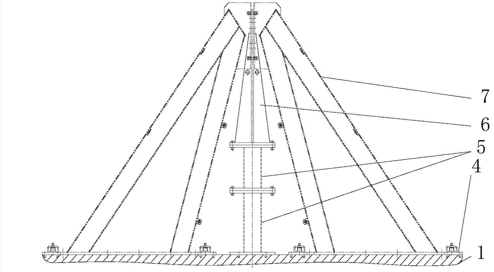
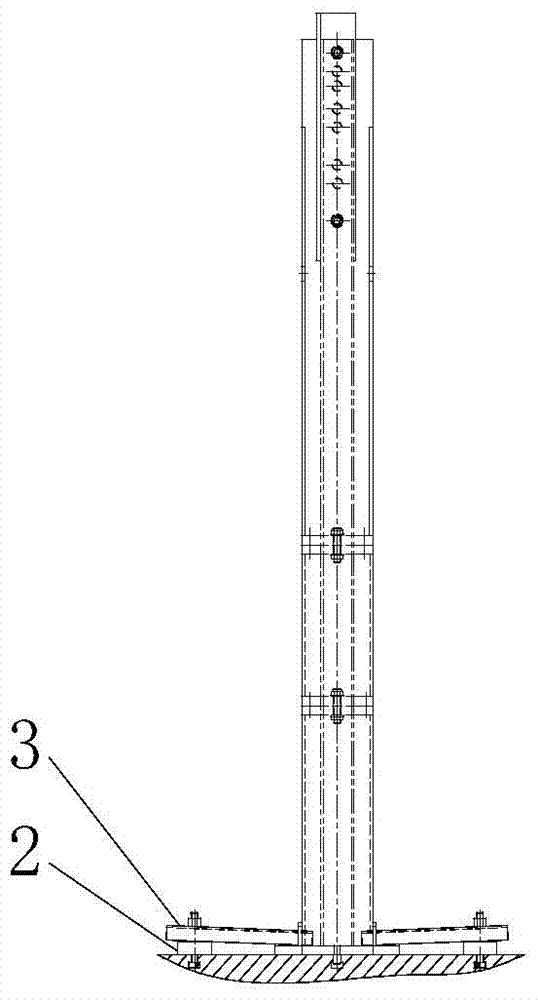
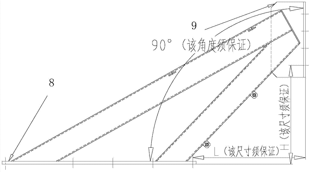
[0036] An oil-immersed power transformer oil conservator bracket assembly welding device, used to realize the welding operation between the oil conservator bracket, the oil conservator foot fixing plate, and the oil tank side wall fixing plate, such as figure 1 , 2 As shown, including welding platform, backing plate, pressure plate, horizontal positioning plate, riser block and vertical positioning plate,

[0037] The welding platform is a rectangular platform with four T-shaped grooves in the length direction, which are used to carry the oil conservator bracket, the side wall fixing plate of the oil tank and other components of the assembly welding device, and keep them in the welding process. stability;

[0038] The backing plate is a square with a through hole in the center, and is located between the pressing plate and the welding platform, so as ...


PUM


Abstract

The invention discloses an oil immersed power transformer conservator support assembling and welding device and a welding method thereof. The device is used for welding a conservator support with a conservator supporting leg fixing plate and welding oil tank side wall fixing plates, and comprises a welding platform, a base plate, a pressing plate, a horizontal positioning plate, a heightening block. The welding platform is rectangular, four T-shaped grooves are formed in the length direction of the welding platform for bearing the conservator support, the oil tank side wall fixing plates and other parts of the assembling and welding device, and stability and the like in the welding process are kept. The device has the advantages of positioning accuracy, high assembly precision, simplicity in operation, convenience in use, high efficiency in operation, high universality, small welding deformation and the like. After the device and the method are implemented, various specifications of manufactured transformer conservator supports can be smoothly assembled once in the general assembly process of a transformer oil tank, any reworking is avoided, and fine effects are achieved.

Description

technical field [0001] The invention is used for the assembly and welding of the support of the oil conservator, and in particular is an assembly and welding device for the support of the oil conservator of the oil-immersed power transformer. Background technique [0002] In the prior art, the assembly and welding of the oil conservator bracket is mostly done manually. After the oil tank bracket, the oil conservator foot fixing plate and the oil tank side wall fixing plate are processed according to the size, they are directly assembled and welded manually. This method is suitable for large For workpieces of different sizes, it is difficult to guarantee the accuracy and the error is relatively large, especially the positioning dimensions and verticality dimensions of the oil conservator foot fixing plate and the oil tank side wall fixing plate cannot be guaranteed, and due to the influence of temperature during the welding process. It causes welding deformation of the workpi...

Claims


Application Information

Patent Timeline
Patent Type & Authority Applications(China)
IPC IPC(8): B23K37/04
CPCB23K37/04B23K37/0461B23K2101/36
Inventor 卢旭日俞高波
Owner SANBIAN SCI TECH
Learn More