Wagon brake pull rod limiting carrier

A brake lever and limit technology, which is applied in railway braking systems, operating mechanisms of railway vehicle brakes, railway car body parts, etc.

Active Publication Date: 2014-01-01
CRRC SHIJIAZHUANG CO LTD
View PDF5 Cites 2 Cited by
  • Summary
  • Abstract
  • Description
  • Claims
  • Application Information

AI Technical Summary

Problems solved by technology

In the prior art, because there is no limit device on both sides of the brake rod, it often deviates left and right during use, and the head of the brake rod is stuck by both sides of the web hole, resulting in unsmooth reset of the brake rod

Method used


Image

  • Wagon brake pull rod limiting carrier
  • Wagon brake pull rod limiting carrier

Examples


Embodiment 1

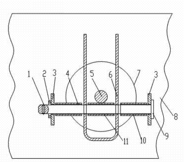
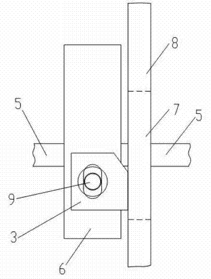
[0011] Embodiment 1: A limit bracket for a brake rod of a railway freight car, comprising a beam web 8, a supporting plate 3, a T-shaped pin 9 and a brake rod 5; Vertical connection below, in the middle part of beam web 8, be provided with perforation 7, described supporting plate 3 is connected on the beam web 8 on the left and right sides of perforation 7, is provided with hole on supporting plate 3, and described T shape pin 9 passes through the hole of the supporting plate 3, the brake pull rod 5 is located on the T-shaped pin shaft 9 and passes through the perforation 7; it is characterized in that: a U-shaped baffle 6 is also provided, and the opening of the U-shaped baffle 6 It faces upward and has holes on the two side walls. The T-shaped pin shaft 9 passes through the hole of the supporting plate 3 and the hole of the U-shaped baffle plate 6, and is set on the T-shaped pin shaft 9 inside the U-shaped baffle plate 6. There is a first sleeve 11, and the second sleeve 4 ...

Embodiment 2

[0012] Embodiment 2: A limit bracket for the brake rod of a railway freight car, including a beam web 8, a supporting plate 3, a T-shaped pin 9 and a brake rod 5; Vertical connection below, in the middle part of beam web 8, be provided with perforation 7, described supporting plate 3 is connected on the beam web 8 on the left and right sides of perforation 7, is provided with hole on supporting plate 3, and described T shape pin 9 passes through the hole of the supporting plate 3, the brake pull rod 5 is located on the T-shaped pin shaft 9 and passes through the perforation 7; it is characterized in that: a U-shaped baffle 6 is also provided, and the opening of the U-shaped baffle 6 It faces upward and has holes on the two side walls. The T-shaped pin shaft 9 passes through the hole of the supporting plate 3 and the hole of the U-shaped baffle plate 6, and is set on the T-shaped pin shaft 9 inside the U-shaped baffle plate 6. There is a first sleeve 11, and the second sleeve 4...


PUM


Abstract

The invention discloses a wagon brake pull rod limiting carrier. The wagon brake pull rod limiting carrier comprises a cross beam web, carrying plates, a T-shaped pin and a brake pull rod. The upper end of the cross beam web is perpendicularly connected with the lower face of a bottom plate of a railway vehicle. A through hole is formed in the middle of the cross beam web. The carrying plates are connected to the cross beam web on the left side and the right side of the through hole. Holes are formed in the carrying plates, the T-shaped pin penetrates the holes of the carrying plates, and the brake pull rod is positioned on the T-shaped pin and penetrates the through hole. The wagon brake pull rod limiting carrier is characterized in that the limiting carrier is further provided with a U-shaped retaining plate, an opening of the U-shaped retaining plate faces upwards and holes are formed in two side walls of the U-shaped retaining plate, the T-shaped pin penetrates the holes of the carrying plates and the holes of the U-shaped retaining plate, a first sleeve is sleeved on the T-shaped pin inside the U-shaped retaining plate, a second sleeve and a third sleeve are sleeved on the T-shaped pin on two sides of the U-shaped retaining plate respectively, and the brake pull rod is positioned on the first sleeve inside the U-shaped retaining plate. By the U-shaped retaining plate, the brake pull rod can be prevented from deviating leftwards and rightwards and is enabled to reset successfully.

Description

technical field [0001] The invention relates to the technical field of railway vehicle braking. Background technique [0002] The brake rods of railway vehicles generally pass through the web holes of the beams of the underframe. can be pulled vertically. In the prior art, because there is no limit device on both sides of the brake rod, it often deviates left and right during use, and the head of the brake rod is stuck by both sides of the web hole, resulting in unsmooth reset of the brake rod. Contents of the invention [0003] The technical problem to be solved by the present invention is to provide a brake rod limit bracket for railway wagons, which has the characteristics of preventing or reducing the left and right deviation of the brake rod and making the brake rod reset smoothly. [0004] In order to solve the above-mentioned technical problems, the technical solution adopted by the present invention is: a brake rod limit bracket for railway wagons, including a be...

Claims


Application Information

Patent Timeline
Patent Type & Authority Applications(China)
IPC IPC(8): B61H13/00
Inventor 曹宝刚许秀峰张宝山
Owner CRRC SHIJIAZHUANG CO LTD
Why Eureka
Try Eureka