Process and apparatus for coating composite pulp honeycomb support elements

a technology of honeycomb support elements and composite pulp, which is applied in the field of coating devices for coating composite pulp honeycomb support elements, can solve the problems of large-scale use of known art methods, affecting the fire resistance of composite honeycomb support elements, and thereby dissolving

Active Publication Date: 2018-08-28
ISELI FREDY
View PDF27 Cites 0 Cited by
  • Summary
  • Abstract
  • Description
  • Claims
  • Application Information

AI Technical Summary

Benefits of technology

[0015]By means of the invention a continuously operating coating device is therefore created, and a coating method is proposed in which impregnation agent flows, preferably at atmospheric pressure, from above into the passages, preferably aligned at right angles to a direction of feed, and is built up in the latter for a limited period of time until it flows past appropriate damming agents, preferably such that the passages are coated over the whole of their periphery; this can be achieved in that the impregnation agent is built up at least as far as the upper edge of the passages, preferably even above the latter, i.e. it is particularly expedient if the feed velocity is coordinated with the filling velocity, i.e. the flow velocity of the impregnation agent into the passages, such that impregnation agent builds up for a certain period of time on the upper face of the composite pulp honeycomb support elements. In that the composite pulp honeycomb support element, in particular continuously, very especially preferably during the filling process, is moved further in the direction of feed to a draining station the action of the impregnation agent in the filled passages is small in terms of time, i.e. the risk of an impermissibly severe softening of the composite pulp honeycomb support elements, and thus damage to the honeycomb structure, is advantageously avoided.
[0018]In overall terms a comparatively cost-effective device is proposed, together with a method that can be implemented cost effectively, which in comparison to the methods of known art is distinguished in terms of a high throughput, and low energy consumption.

Problems solved by technology

While the synthetic resin systems coming into use possibly increase the water resistance, they do not increase the fire resistance of the composite honeycomb support element.
Moreover, large-scale use of the method of known art turns out to be difficult, because only a batch process can be undertaken.
Also, with the method of known art the passages of the composite honeycomb support element cannot be coated with aqueous impregnation agents, since the paper honeycombs suck up the water and thereby lose strength; the honeycomb structure becomes soft and thereby disintegrates.
The coating device of known art does not operate continuously, but rather in batch mode, which is disadvantageous with regard to the coating rate.
Moreover, the coating device and the coating method of known art are not suitable for coating with impregnation coatings containing cement, since these would clog up and / or soften the much thinner passages of corrugated board composite honeycomb support elements.
Such a procedure is only possible with the foam coating material as described, which has a low density and a high viscosity.
If a cement coating were to be used, the passages would inevitably clog up.
The methods of known art are not suitable for the purpose of coating composite pulp honeycomb support elements with an impregnation coating, in particular, an impregnation coating containing cement for the purpose of increasing the fire and water resistance, and / or the mechanical stability.

Method used


Image

  • Process and apparatus for coating composite pulp honeycomb support elements

Examples


Embodiment Construction

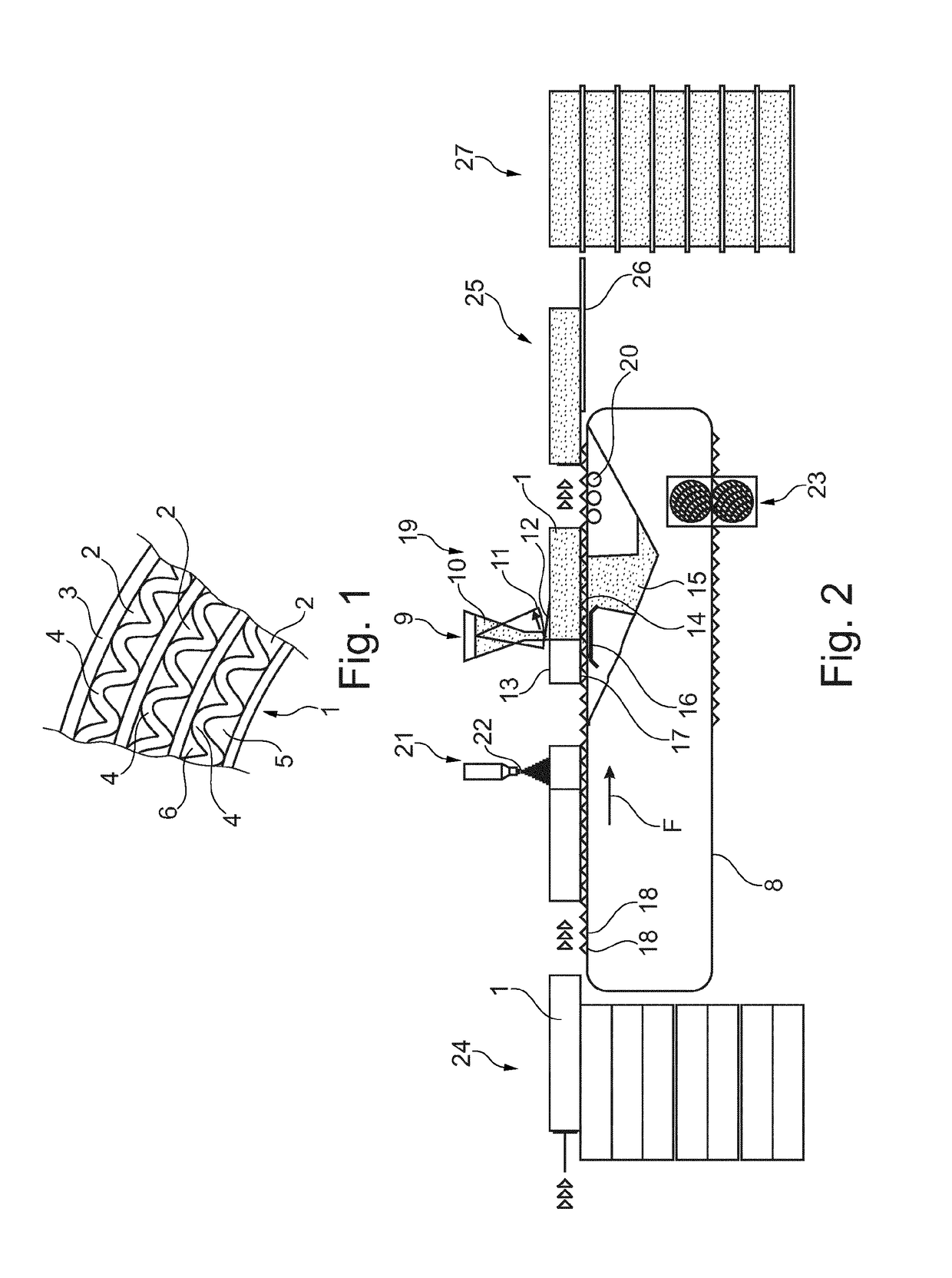
[0035]FIG. 1 shows a plan view onto a face of a composite pulp honeycomb support element 1 (here in the exemplary form of a corrugated board honeycomb body). The detail shown consists of three plies 2 (layers) glued together, wherein each ply 2 is formed from a flat carrier paper 3, which is glued together with a corrugated paper 4 to form (first) axial passages 5. The passages 5 are thus peripherally bounded by the corrugated paper 4 and the carrier paper 3. Furthermore each ply 2 comprises (second) passages 6, which in the example of embodiment shown are bounded by the above-cited corrugated paper 4 and a further carrier paper, namely the carrier paper of the adjacent (parallel) ply. In an alternative variant of embodiment, not illustrated, each ply 2 can also comprise two carrier papers, which accommodate the corrugated paper 4 between them in the form of a sandwich. In this case the (second) passages 6 are bounded by the paper and a carrier paper 3 of the same ply.

[0036]As can b...


PUM

PropertyMeasurementUnit
heightaaaaaaaaaa
heightaaaaaaaaaa
heightaaaaaaaaaa

Abstract

A coating device for coating composite cellulose honeycomb support parts (1) each having a multiplicity of channels (5, 6) extending in an axial direction with an impregnation coating to increase fire, water-resistance and / or mechanical stability of the support parts (1). A conveyor (8) transports the support parts (1) in a conveying direction along a filling station (9) configured to pour impregnation agent (12) from above into the channels (5, 6), and damming agents (16) are configured such that the impregnation agent (12) is prevented or at least delayed from draining downwards out of the channels (5, 6) such that the impregnation agent (12) builds up in the channels (5, 6). An emptying station (19) is arranged downstream of the filling station (9) in the conveying direction, at which emptying station excess impregnation agent (12) drains out of the channels (5, 6) in the composite cellulose honeycomb support parts (1). A corresponding process is also disclosed.

Description

BACKGROUND OF THE INVENTION[0001]The invention relates to a coating device for coating composite pulp (cellulose) honeycomb support elements, each having a multiplicity of passages extending in an axial direction, with an impregnation coating for the purpose of increasing the fire and / or water resistance and / or the mechanical stability. The invention furthermore relates to a coating method for the purpose of coating such pulp sheets.[0002]Composite honeycomb support elements are of known art, in particular when deployed as a honeycomb core material in composite sheets, wherein the honeycombs of the composite honeycomb support elements are formed from a multiplicity of passages extending in an axial direction, which as a rule are peripherally bounded by carrier papers, together with corrugated papers glued together with the carrier papers.[0003]A method for the manufacture of composite honeycomb support elements is, for example, described in DE 103 05 747 A1. Other composite honeycom...

Claims


Application Information

Patent Timeline
Patent Type & Authority Patents(United States)
IPC IPC(8): B31D3/02B05C7/04B05C13/02B05C11/10B05C5/00B32B29/00B29D99/00D21H23/48B05D7/22B32B3/12B29K311/12
CPCB05C7/04B05C11/1039B05C13/02B05D7/22B29D99/0089B31D3/02B31D3/0292B32B3/12B32B29/005D21H23/48B05C5/005B32B2307/7265B29K2311/126B32B2250/26B32B2260/028B32B2260/046B32B2307/3065
Inventor ISELI, FREDY
Owner ISELI FREDY
Why Eureka
Try Eureka