Non-destructive form brackets and methods of using the same

a form bracket and non-destructive technology, applied in the field of tilting construction, can solve the problem that nails b>16/b> are driven directly into the concrete foundation

Active Publication Date: 2006-08-29
SHAW LEE A +1
View PDF9 Cites 14 Cited by
  • Summary
  • Abstract
  • Description
  • Claims
  • Application Information

AI Technical Summary

Benefits of technology

[0012]An advantage of the non-destructive form bracket assembly is that it requires no drilling or driving of fastening hardware such as nails into existing foundation surfaces. As a result, structural damage to the foundation can be effectively eliminated. Another advantage of the present invention is that it utilizes readily available existing brackets to save manufacturing and tooling costs. A further advantage of the non-destructive form bracket is that the form can be aligned to snap line or layout with the brackets pre-installed. As a result, another advantage of the present invention is that the brackets can stay on the forms for re-use. Additionally, a single rail bracket may be used to secure single rail tilt-up forms without drilling slabs.
[0013]According to a first embodiment of the present invention, a non-destructive form bracket assembly is provided. The bracket assembly comprises a bracket having a vertical supporting side and horizontal supporting side for maintaining a form vertically upright; an attachment device having a first and second foundation attachment portion. The attachment device is adapted for engaging a portion of the bracket for non-destructively affixing the bracket to a foundation. Adhesive is affixed to bottom surfaces of the first and second foundation attachment portions for adhering the attachment to the foundation.
[0014]According to another aspect of the present invention, the bracket comprises a triangular shaped gusset attached to the vertical supporting side and the horizontal supporting side, a hypotenuse side interconnecting the vertical and horizontal supporting sides. The gusset has a triangular void therethrough such that a horizontally oriented raised gusset edge is formed directly above the horizontal supporting side. A mounting tab is formed contiguously along each of the vertical and horizontal supporting sides, and the mounting tabs are oriented at right angles relative to the gusset and having a plurality of mounting holes.
[0015]According to another aspect of the present invention, the bracket comprises a SIMPSON concrete form angle. Furthermore, the attachment device may comprise an attachment plate adapted to hold the horizontally oriented raised gusset edge downward towards the foundation.
[0016]According to another aspect of the present invention, the attachment plate comprises an inclined portion connected to the first foundation attachment portion, a vertical portion connected to the inclined portion forming a retaining edge positioned within a triangular shaped recess, and second foundation attachment portion connected to the vertical portion such that the first and second attachment portions are oriented in a same plane.
[0017]According to another aspect of the present invention, the attachment plate is adapted to be transversely positioned over the horizontally oriented raised gusset edge such that the retaining edge engages the raised gusset edge. Furthermore, the mounting tab formed on the horizontal supporting side fits within the triangular shaped recess without obstruction.

Problems solved by technology

The main disadvantage of the aforementioned process for forming tilt-up concrete walls, is that the nails 16 are driven directly into the concrete foundation 18.

Method used


Image

  • Non-destructive form brackets and methods of using the same
  • Non-destructive form brackets and methods of using the same
  • Non-destructive form brackets and methods of using the same

Examples


first embodiment

OF THE PRESENT INVENTION

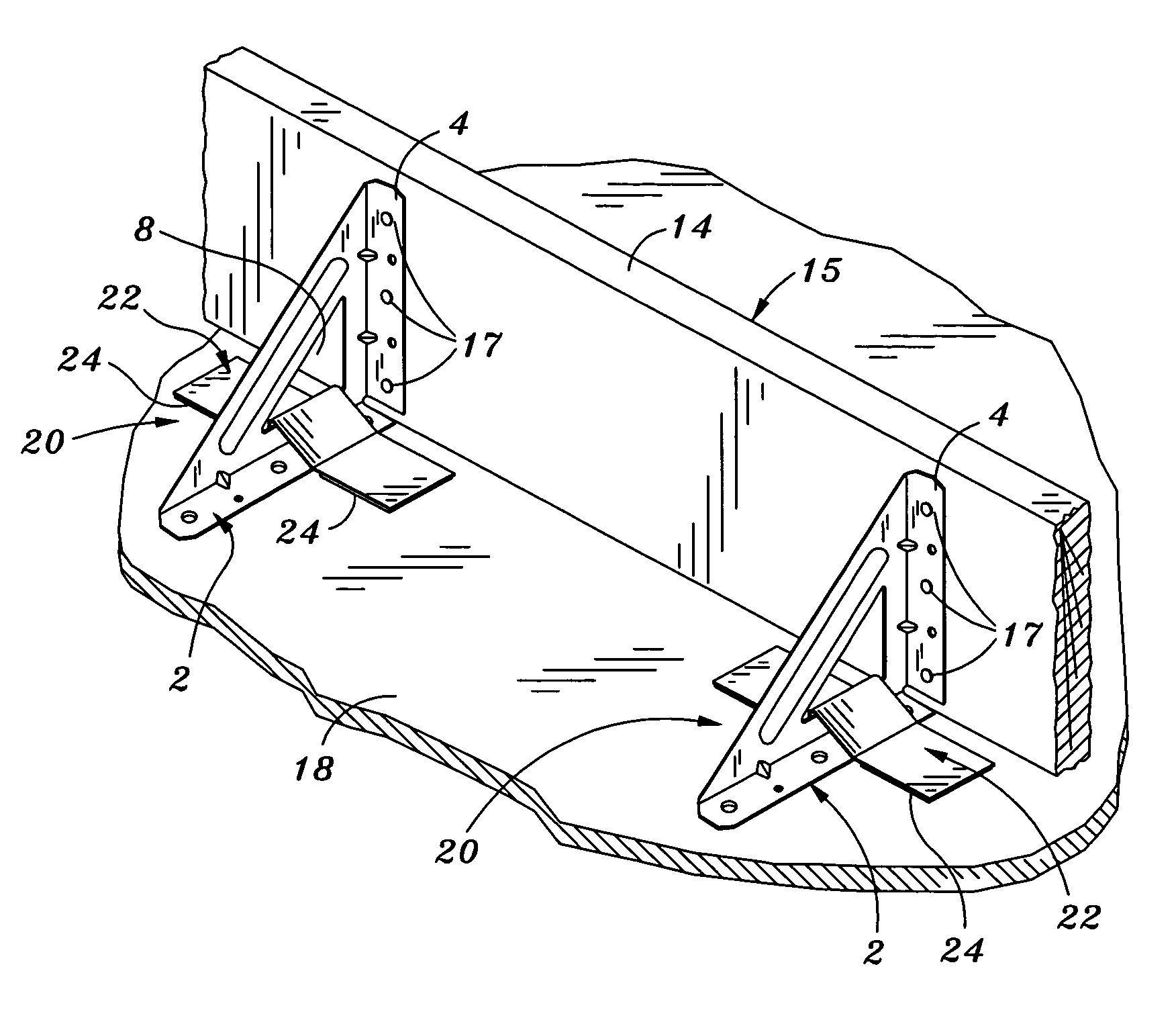
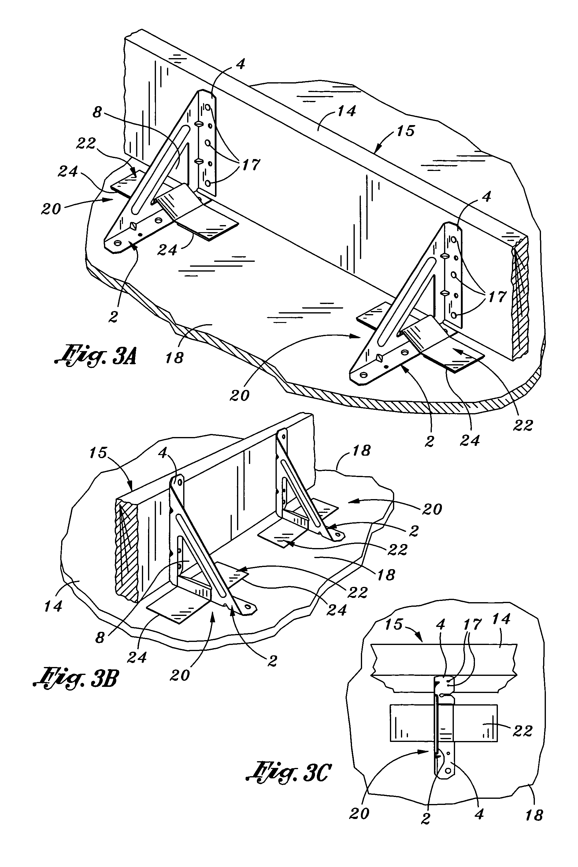
[0043]FIGS. 3A–B illustrate rightside and leftside perspective views of a plurality of non-destructive form bracket assemblies 20 utilized in a form installation, according to a first embodiment of the present invention. Also FIG. 3C is provided to illustrate a top view perspective of the non-destructive form bracket assembly 20 utilized in the form installation, according to the first embodiment of the present invention.

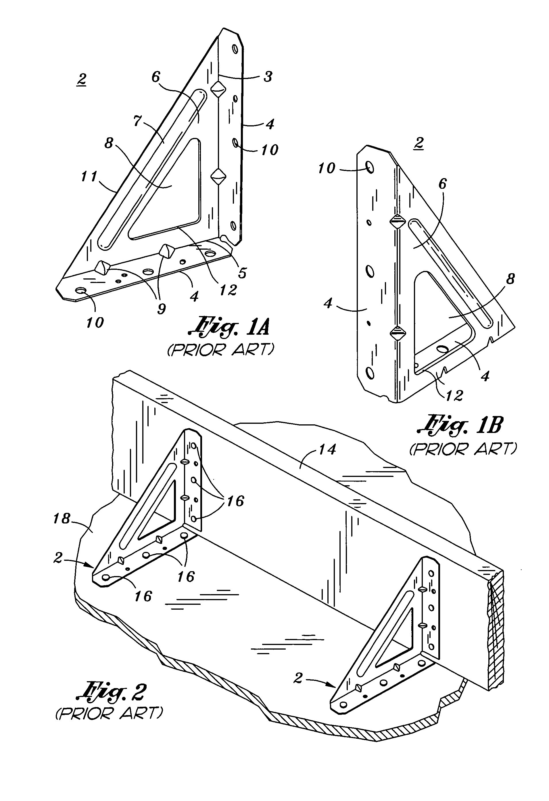
[0044]The non-destructive form bracket assembly 20 comprises a prior art SIMPSON bracket 2 and an attachment plate 22. FIG. 4A illustrates a top view perspective of an attachment plate 22, FIG. 4B illustrates a side view perspective of the attachment plate and FIG. 4C illustrates a bottom view perspective of the attachment plate, according to an aspect of the present invention.

[0045]The attachment plate 22 plate may be formed from sheet metal, preferably galvanized. The attachment plate 22 includes a first planar foundation attachment portion...

second embodiment

OF THE PRESENT INVENTION

[0051]FIG. 6A illustrates top view perspective of a second embodiment of a non-destructive form bracket which is a single rail bracket 50, according to an aspect of the present invention. The single rail bracket 50 is a basic U-shaped bracket having a horizontally oriented planar foundation attachment portion 52 disposed between two opposing vertically oriented sidewall portions 54, 56. The foundation attachment portion 52 has a width which is adapted to accept a standard cut lumber such as 2×'s or 1×'s. A plurality of mounting holes 10 are disposed on the vertically oriented sidewall portions 54, 56 which are adapted to receive fastening hardware such as nails or screws 16. On the bottom of the foundation attachment portion 52, a double-sided adhesive strip 24 is applied to the bottom face of the foundation attachment portions 52. Before the foundation portion 52 is applied to the foundation 18, a cover sheet or the like is peeled from the adhesive strip 24....


PUM


Abstract

A non-destructive form bracket assembly and method of using the same is provided including a bracket having a vertical supporting side and horizontal supporting side for maintaining a form vertically upright; an attachment device having a first and second foundation attachment portion. The attachment device is adapted for engaging a portion of said bracket for non-destructively affixing the bracket to a foundation. Adhesive is affixed to bottom surfaces of the first and second foundation attachment portions for adhering the attachment to the foundation. Additionally, a non-destructive form assembly utilized in tilt-up construction for a double-side pour process is provided comprising a form and a plurality of U-shaped single rail brackets installed on a bottom edge of the form in spaced intervals with pre-applied adhesive on the bottom of the brackets.

Description

CROSS-REFERENCE TO RELATED APPLICATIONS[0001]Not ApplicableSTATEMENT RE: FEDERALLY SPONSORED RESEARCH / DEVELOPMENT[0002]Not ApplicableBACKGROUND OF THE INVENTION[0003]1. Field of the Invention[0004]The present invention relates to tilt-up construction. In particular, the present invention relates to brackets used to support form sides. And in more particularity, the present invention relates to non-destructive form brackets which eliminate the use of concrete nails as a means of attaching form brackets to the floor slab or foundation.[0005]2. Background of the Invention[0006]Tilt-up construction is one of the fastest growing industries in the United States. At least 10,000 buildings enclosing more than 650 million square feet are constructed annually. This is due, in part, to the economics of tilt-up, which combine reasonable cost with low maintenance, durability, speed of construction, and minimal capital investment. The tilt-up process requires few forms and makes efficient use of ...

Claims


Application Information

Patent Timeline
Patent Type & Authority Patents(United States)
IPC IPC(8): E04G17/00E04G13/00E04G17/14E04G21/16F16M11/00
CPCE04G13/00E04G21/16E04G17/14
Inventor SHAW, LEE A.SHAW, RONALD D.
Owner SHAW LEE A
Why Eureka
Try Eureka