
Method for drilling holes and optionally inserting fasteners

a technology of fasteners and drilling holes, which is applied in the direction of drilling/boring measurement devices, manufacturing tools, transportation and packaging, etc., can solve the problems of ineffective structure for its intended purpose, subject to the expense of repair or replacement, and the gap between the drilled layer and the next layer to develop, so as to reduce the time and expense involved

Inactive Publication Date: 2007-01-16
THE BOEING CO
View PDF20 Cites 18 Cited by
  • Summary
  • Abstract
  • Description
  • Claims
  • Application Information

AI Technical Summary

Benefits of technology

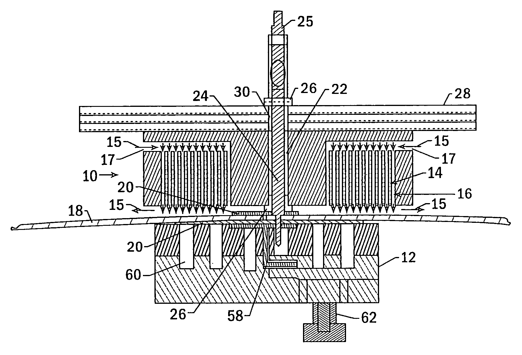
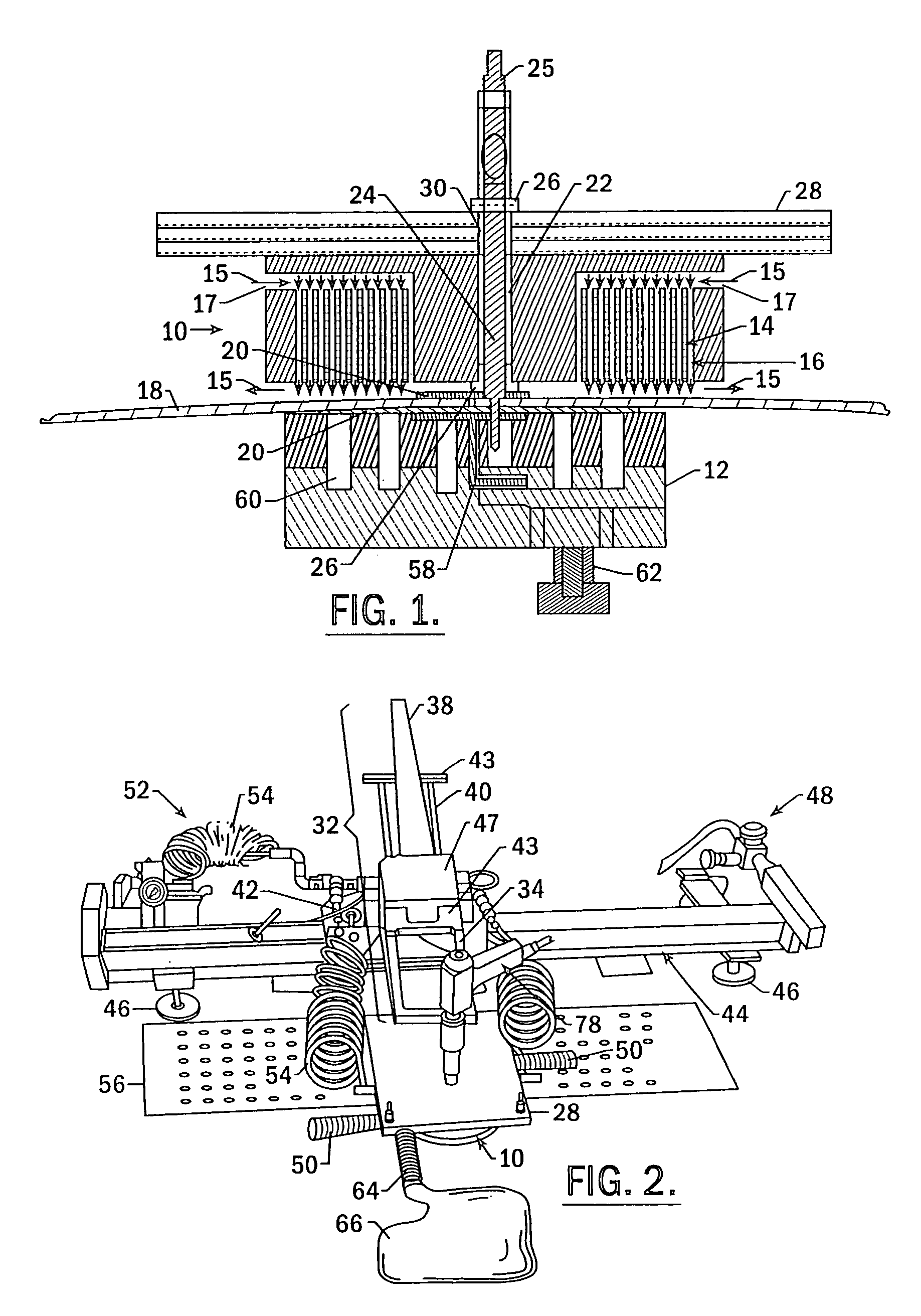
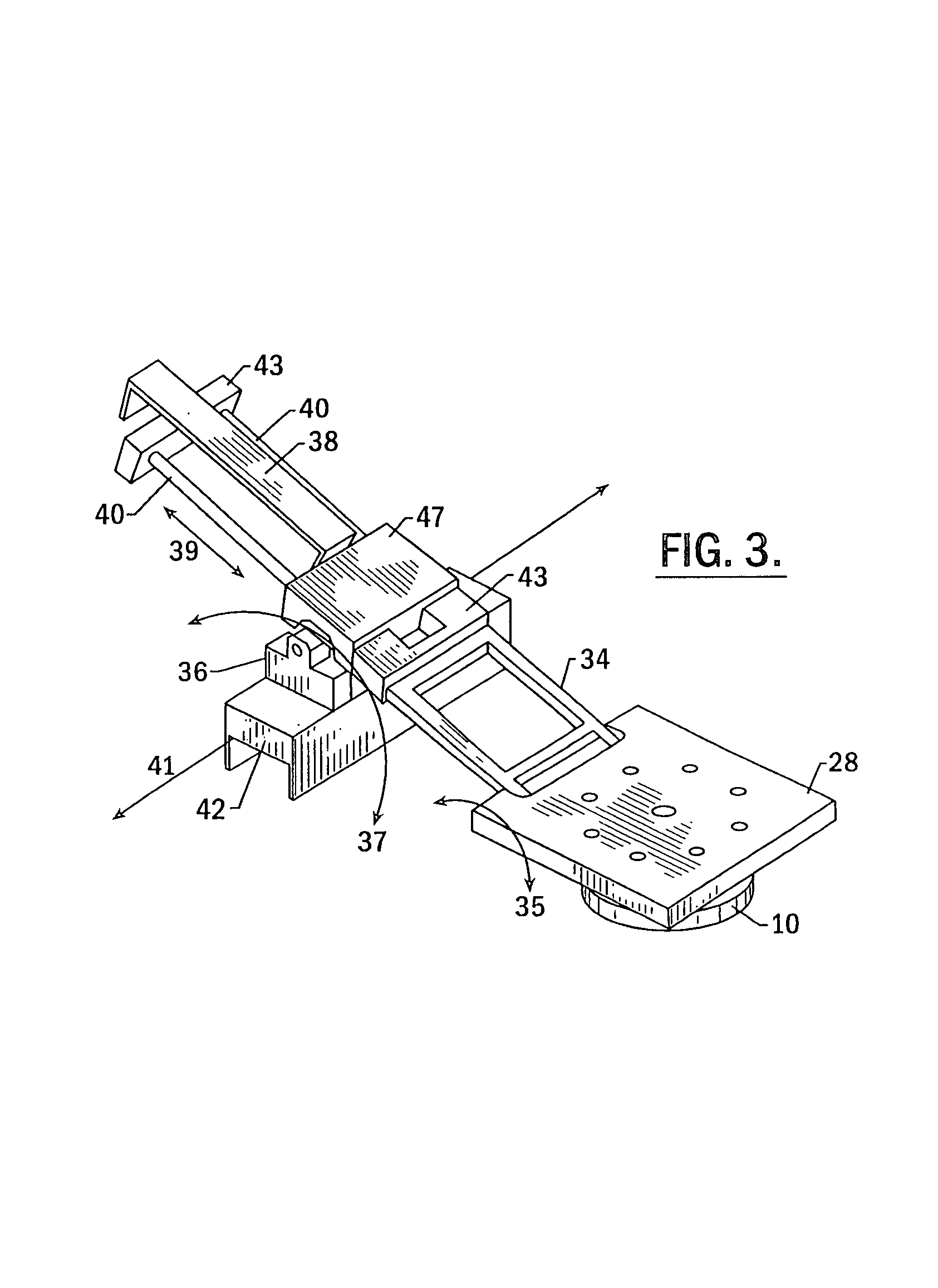
[0008]The apparatus and method for drilling holes and optionally inserting fasteners of the present invention reduce the time and expense involved in the manufacture of a multi-layer structure by eliminating the need to disassemble the drilled layers in order to de-burr the holes and clean the debris from the layers before reassembling and sealing the layers and countersinking the holes. The apparatus and method of this invention provide for drilling holes, such as countersunk holes, in sealed, tightly held layers of a structure and optionally inserting fasteners in the holes such that the process is completed in one efficient operation. The layers of the structure are held together by an electromagnet through which a drilling tool may extend and a clamp at least partially made of magnetic material, such that a hole may be drilled through the layers without creating burrs or allowing debris to accumulate between the layers. A fastener may be then immediately inserted in the hole.
[0011]To align the clamp with the electromagnet, the clamp may be capable of being slidably mounted to the structure, such that the clamp may slide to a position opposite and aligned with the electromagnet. In addition, grooves may extend through the clamp in the direction in which the clamp is capable of sliding, such that the clamp may slide over the structure surface without obstruction from previously installed fasteners or other protrusions from the structure. The clamp may include a layer of non-abrasive material on the side of the clamp that faces the structure for ease of sliding the clamp and to prevent the clamp from harming the structure while sliding. Furthermore, the electromagnet and / or the clamp may have an alignment indicator to indicate when the openings of the clamp and the electromagnet are aligned.
[0017]The apparatus and method of the present invention also include a fastener insertion device and a method of inserting a fastener in a hole defined by a work piece that includes a supply of fasteners, a tube with an opening that is larger than the fastener, and an air flow generator, such as a vacuum source or an air pump, to create air flow in through the tube and out toward the work piece. As such, when the tube is aligned with the hole defined in the work piece and the fastener is placed in the tube, the air carries the fastener through the tube, then inserts it into the hole in the work piece. In some embodiments the fastener may be carried through the tube, through the air flow generator, then into the hole in the work piece. Aligning the tube opening with the work piece hole may include aligning the tube opening with an opening in a template that is aligned with the work piece hole. The tube may have openings about the circumferential surface of the tube to prevent the fastener from inhibiting the air flow when it is placed in the tube. In addition, the air flow may be laminar. As such, fasteners may be efficiently inserted in the holes that have been drilled in the multi-layer structure.

Problems solved by technology

Thus, if burrs, debris and / or excessive sealant are present, then the layers cannot be properly fastened and the layers may suffer corrosion, cracking and / or premature fatigue failure, which generally renders the structure ineffective for its intended purpose and, therefore, subject to the expense of repair or replacement.
This can cause a gap to develop between a drilled layer and the next layer, particularly when the layers are a stack up of thin material.
The gap between the layers causes burrs about the hole and debris is likely to gather between the layers.
Thus, once the holes are drilled, the layers must be disassembled, the burrs must be removed from the holes, and the debris must be cleaned from the surfaces of the layers, all of which is a time-consuming and labor intensive process.
Overall, this process is expensive, laborious, and time-consuming.
In addition, the integrity of the resulting holes depends upon the completion of many manual processes, which creates a risk that certain steps may be performed inadequately or completely overlooked.

Method used


Image

  • Method for drilling holes and optionally inserting fasteners
  • Method for drilling holes and optionally inserting fasteners
  • Method for drilling holes and optionally inserting fasteners

Examples


Embodiment Construction

[0026]The present inventions now will be described more fully hereinafter with reference to the accompanying drawings, in which some, but not all embodiments of the invention are shown. Indeed, these inventions may be embodied in many different forms and should not be construed as limited to the embodiments set forth herein; rather, these embodiments are provided so that this disclosure will satisfy applicable legal requirements. Like numbers refer to like elements throughout.

[0027]The method and apparatus for drilling holes and optionally inserting fasteners of the present invention provide for efficiently drilling holes through a multiple-layer structure because the layers are securely held together during the drilling by an electromagnet and a clamp, each on opposite sides of the structure. The electromagnet and clamp hold the layers together so tightly that the layers do not have to be disassembled after drilling in order to de-burr the holes and remove the debris from between t...


PUM

PropertyMeasurementUnit
air velocityaaaaaaaaaa
timeaaaaaaaaaa
dynamic forcesaaaaaaaaaa

Abstract

The method and apparatus for drilling holes and optionally inserting fasteners of the present invention provide for efficiently drilling holes through a multiple-layer structure because the layers are securely held together during the drilling by an electromagnet and a clamp, each on opposite sides of the structure. The electromagnet and clamp hold the layers together so tightly that burrs do not form within the holes and debris does not accumulate between the layers and, therefore the layers do not have to be disassembled after drilling. In addition, the apparatus and method of the present invention provide for initially drilling the hole with a countersink and for inserting a fastener into the hole, through the electromagnet, immediately after drilling the hole, such that the hole does not have to be revisited after reassembly and drying of the sealant in order to drill a countersink and / or insert a fastener.

Description

CROSS-REFERENCE TO RELATED APPLICATIONS[0001]This application is a divisional of U.S. application Ser. No. 10 / 158,285, filed May 30, 2002 now U.S. Pat. No. 6,905,291, which is hereby incorporated herein in its entirety by reference.BACKGROUND OF THE INVENTION[0002]The present invention relates to enabling an operator to drill holes and optionally insert fasteners, and, in particular to drilling holes and optionally inserting fasteners through multi-layer structures by utilizing an electromagnet assembly to securely clamp the multi-layer structure together during the operation.[0003]The fasteners that hold together multi-layer structures, particularly those structures that are subject to significant dynamic forces and / or pressure over their lifetime, such as aircraft bodies, bridges, vehicle bodies, buildings, and others, must be properly secured in order to ensure that the structure will perform as intended over its lifetime. In order to properly secure a fastener in a multi-layer s...

Claims


Application Information

Patent Timeline
Patent Type & Authority Patents(United States)
IPC IPC(8): B23P11/00B23B47/00B23B49/02
CPCB21J15/14B23B49/026B23P19/10B21J15/142Y10T408/50B23B2215/04B23B2250/12B23B2260/03B23B2260/124B23B2270/38Y10T408/56245Y10T29/49995Y10T29/5343Y10T408/563Y10T408/03Y10T408/554Y10T29/49947Y10T29/5118Y10T408/97B21J15/32
Inventor DAY, ARTHURSTANLEY, BRUCE DAVID
Owner THE BOEING CO
Learn More