Negative pressure spinning device and negative pressure spinning method for roving frame

A spinning device and roving frame technology, which is applied to spinning machines, continuous winding spinning machines, textiles and papermaking, etc. It can solve the problems of restricting compression space, heavy labor intensity, and reducing the adhesion of spinning pile tapes, etc. problems, to achieve the effect of improving utilization rate and reducing labor intensity of workers

Active Publication Date: 2016-02-03
江苏世纪纺织有限公司
View PDF13 Cites 0 Cited by
  • Summary
  • Abstract
  • Description
  • Claims
  • Application Information

AI Technical Summary

Problems solved by technology

At the same time, when the yarn bobbin is used for too long, due to the adhesion of the velvet tape at the threading part, a layer of fiber will often be attached to the velvet tape, thereby reducing the adhesion of the velvet tape and affecting the threading effect.
[0003] Due to the above-mentioned technical defects of the traditional roving frame, in the actual production process, it often needs to be remedied or replaced by manual auxiliary spinning. Therefore, the factory using the traditional roving frame requires a large amount of labor in the winding process.
On the one hand, this restricts the space for the spinning mill to compress the unit product cost; on the other hand, the labor intensity of the head raising process is very heavy and requires a large number of skilled operators

Method used


Image

  • Negative pressure spinning device and negative pressure spinning method for roving frame
  • Negative pressure spinning device and negative pressure spinning method for roving frame

Examples


Embodiment Construction

[0020] The present invention provides a negative pressure spin-in device and a negative-pressure spin-in method for a roving frame. In order to make the purpose, technical solution and effect of the present invention clearer and clearer, the present invention will be further described in detail below. It should be understood that the specific embodiments described here are only used to explain the present invention, not to limit the present invention.

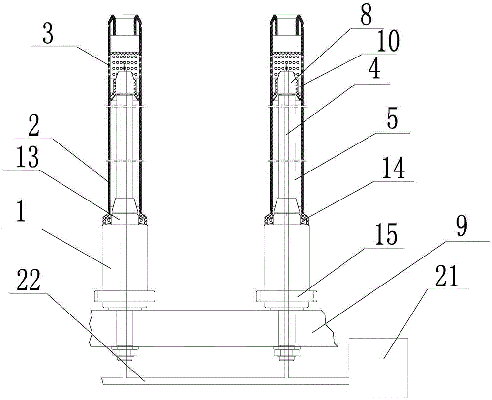
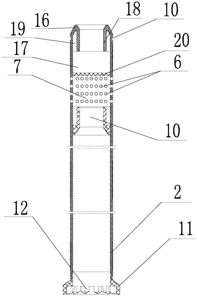
[0021] The invention provides a negative pressure spinning device for a roving frame, such as figure 1 As shown, it includes at least one rotatable bobbin wheel assembly 1, and the upper end of each bobbin wheel assembly 1 is provided with a linked negative pressure spinning bobbin 2, and the negative pressure spinning bobbin 2 is in the ring A negative pressure adsorption area for roving spinning is formed on the spinning-in area 3; each bobbin wheel assembly 1 is equipped with a lower spindle bar 5 with a suction channel 4, a...


PUM


Abstract

The invention discloses a negative-pressure making-up device and a negative-pressure making-up method for a roving frame. The negative-pressure making-up device comprises at least one rotatable bobbin assembly; the upper end of each bobbin assembly is provided with a negative-pressure making-up spool; the negative-pressure making-up spools are in linkage; a negative-pressure absorption area for roving making-up is formed on an annular making-up area of each negative-pressure making-up spool; each bobbin assembly is provided with a lower spindle blade with an air suction channel; each lower spindle blade penetrates in the corresponding bobbin assembly and the corresponding negative-pressure making-up spool to be connected with the corresponding annular making-up areas; and each air suction channel is communicated with the corresponding negative-pressure absorption area. Negative pressure is formed in a negative-pressure cavity by using a suction fan, negative-pressure holes are formed in walls of the negative-pressure making-up spools, yarns are absorbed by the negative-pressure holes, so that automatic doffing making-up is facilitated, the roving making-up rate reaches 100%, and the labor intensity of workers is reduced. Because the yarns are automatically absorbed on the annular making-up areas with the aid of negative pressure in the rotation process of the negative-pressure making-up spool, the problem that the adhesive force is weakened in the traditional velvet strip making-up process is solved, residue on the yarns is avoided, and roving use ratio is greatly increased.

Description

technical field [0001] The invention relates to a negative pressure spinning device and a negative pressure spinning method for a roving frame. Background technique [0002] The roving bobbin used in the automatic doffing roving frame in the prior art has the same spinning principle, that is, a layer of velvet tape is wrapped on the top or bottom of the roving bobbin, and the yarn is pasted on the velvet tape when spinning starts. , to achieve the purpose of giving birth. The spinning-up rate of the roving is only about 80%, and manual auxiliary spinning is needed, which increases the workload of the roving stopper. When threading, use the flyer to press the palm, so that the yarn is pasted on the velvet belt, so as to achieve the purpose of threading. Due to the influence of the position of the pressing palm of the flyer, especially when the position of the pressing palm does not reach the spinning-in position when spinning starts, the spinning-in of the roving will fail....

Claims


Application Information

Patent Timeline
Patent Type & Authority Patents(China)
IPC IPC(8): D01H9/14D01H1/38
Inventor 崔桂华王成吉刘增喜李建霞周春娟郭加阳
Owner 江苏世纪纺织有限公司
Why Eureka
Try Eureka