Dust collector for road sweepers

A dust collection device and road cleaning technology, which is applied to road cleaning, cleaning methods, construction, etc., can solve the problems of increased power consumption of fans and fan motors, uneven distribution of garbage, and reduced cleaning effects, etc., to achieve good suction effects , low power consumption, strong suction effect

Active Publication Date: 2014-01-01
广西玉柴专用汽车有限公司
View PDF8 Cites 8 Cited by
  • Summary
  • Abstract
  • Description
  • Claims
  • Application Information

AI Technical Summary

Problems solved by technology

The main working part of the road sweeper is the dust suction device. The dust suction device is installed under the chassis of the road sweeper. It is mainly equipped with a suction chamber and a suction pipe. The opening of the suction chamber faces the ground, and one end of the suction pipe passes through the suction The suction port is connected to the suction chamber, and the other end of the suction pipe is connected to the fan on the sweeper. When the sweeper is working, the fan starts to run, and a negative pressure is generated in the suction chamber to suck the garbage and dust on the ground into the sweeper. In the compartment, due to the uneven distribution of garbage on the road, there are usually multiple suction ports. The vacuum device with this structure has more suction ports, and the suction force between the suction ports is offset. As the suction power decreases, the cleaning effect also decreases. When the suction power is increased, the power consumption of the fan and its motor will increase.

Method used


Image

  • Dust collector for road sweepers
  • Dust collector for road sweepers
  • Dust collector for road sweepers

Examples


Embodiment Construction

[0016] The present invention will be described in detail below in conjunction with the accompanying drawings and embodiments.

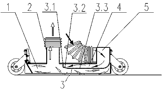
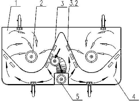
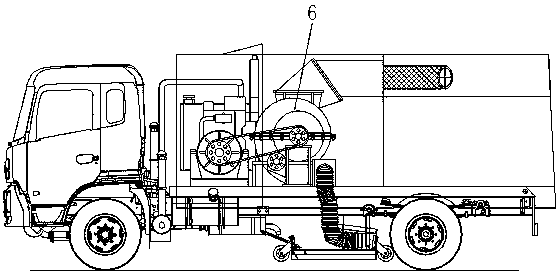
[0017] Such as Figure 1 ~ Figure 4 As shown, the road sweeper dust suction device of the present invention includes a fan 6, a suction chamber 1 and a suction pipe 2, the fan 6 is arranged on the road sweeper, and the suction chamber 1 is formed by a hollow body with the opening facing downward, and the suction There is a suction port in the chamber 1, one end of the suction pipe 2 communicates with the suction chamber 1 through the suction port, and the other end of the suction pipe 2 communicates with the inlet of the fan 6, and the dust suction device of the road sweeper also includes a blow-back pipe 5 and the partition 3, the partition 3 is located in the suction chamber 1, the partition 3 is composed of the bottom wall 3.3 and the front wall 3.1, the bottom wall 3.3 of the partition 3, the front wall 3.1, the upper wall of the suction chamber 1...


PUM


Abstract

The invention relates to a dust collector for road sweepers. The dust collector comprises a fan, a suction chamber and a suction tube. One end of the suction tube is communicated with the suction chamber. The other end of the suction tube is communicated with the fan. The dust collector is characterized by further comprising a back-flushing tube and a partition; the partition is disposed inside the suction chamber and comprises a bottom wall and a front wall, a back-flushing chamber is composed of the bottom wall of the partition, the front wall of the partition, an upper wall of the suction chamber and a side wall of the suction chamber, and the front wall of the partition is corrugated; one end of the back-flushing tube is communicated with the back-flushing chamber, the other end of the back-flushing chamber is communicated with the fan, the connected parts of the suction tube and the suction chamber are arranged at the trough part of the corrugated front wall, and the part of the bottom wall, close to the front wall, is provided with a plurality of blow holes used for blowing up trashes on the ground. The dust collector is good in cleaning effect and low in power consumption.

Description

technical field [0001] The invention relates to the field of sanitation equipment, in particular to a dust suction device for a road sweeper. Background technique [0002] Road sweeper is a kind of sanitation equipment that cleans garbage and dust on the road. Its use can improve the efficiency of road sweeping work, greatly reduce the workload of sanitation workers, and play a very good role in cleaning the road environment. . The main working part of the road sweeper is the dust suction device. The dust suction device is installed under the chassis of the road sweeper. It is mainly equipped with a suction chamber and a suction pipe. The opening of the suction chamber faces the ground, and one end of the suction pipe passes through the suction The suction port is connected to the suction chamber, and the other end of the suction pipe is connected to the fan on the sweeper. When the sweeper is working, the fan starts to run, and a negative pressure is generated in the sucti...

Claims


Application Information

Patent Timeline
Patent Type & Authority Applications(China)
IPC IPC(8): E01H1/08
Inventor 许绍华何洪严明罗健朱擎天李燕黄卫国
Owner 广西玉柴专用汽车有限公司
Why Eureka
Try Eureka