Material binding machine

A binding machine and data technology, applied in binding, printing, etc., can solve the problems of a large number of manual finishing and low work efficiency, and achieve the effect of simple structure, reducing labor intensity, and preventing paper folding or damage

Active Publication Date: 2018-03-06
JIANGSU UNIV OF TECH
View PDF8 Cites 11 Cited by
  • Summary
  • Abstract
  • Description
  • Claims
  • Application Information

AI Technical Summary

Problems solved by technology

[0003] In order to solve the problems in the prior art that many pages of materials need to be sorted and bound after printing, and the work efficiency is low, the present invention provides a data binding machine, which can automatically organize and bind the printed materials into a complete set of materials in order , greatly reducing the labor intensity and improving work efficiency

Method used


Image

  • Material binding machine
  • Material binding machine
  • Material binding machine

Examples


Embodiment 1

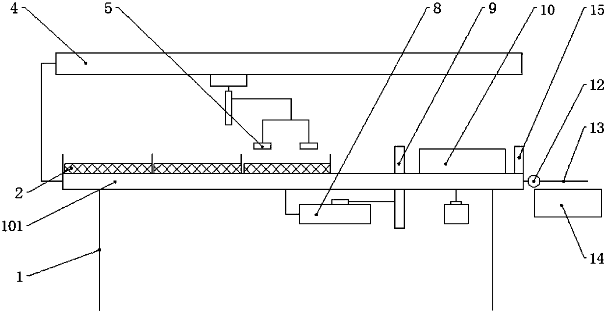
[0034] This embodiment relates to a preferred embodiment of the present invention, in particular to an electrically driven data binding machine, such as Figure 1-4 As shown, the document binding machine includes a paper storage box, a paper picking device, a finishing device, a binding device and a base 1 .

[0035] The bottom plate 101 of the base 1 is provided with a paper storage box, and the paper storage box is a grid area composed of partitions 102 for accommodating paper 2. According to the number of pages of each document, multiple paper storage boxes can be set. box.

[0036] A control platform 4 fixed on the base 1 is arranged above the paper storage box, four vacuum suction cups 5 for absorbing paper 2 are arranged on the control platform 4, and a first driving device for driving the vacuum suction cups 5 is arranged. The first driving device drives the vacuum chuck 5 to move horizontally and up and down between each paper storage box and the sorting area.

[003...

Embodiment 2

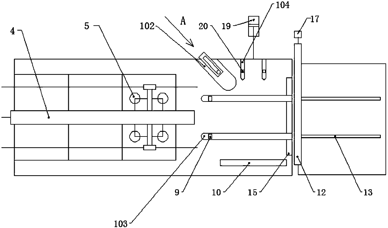
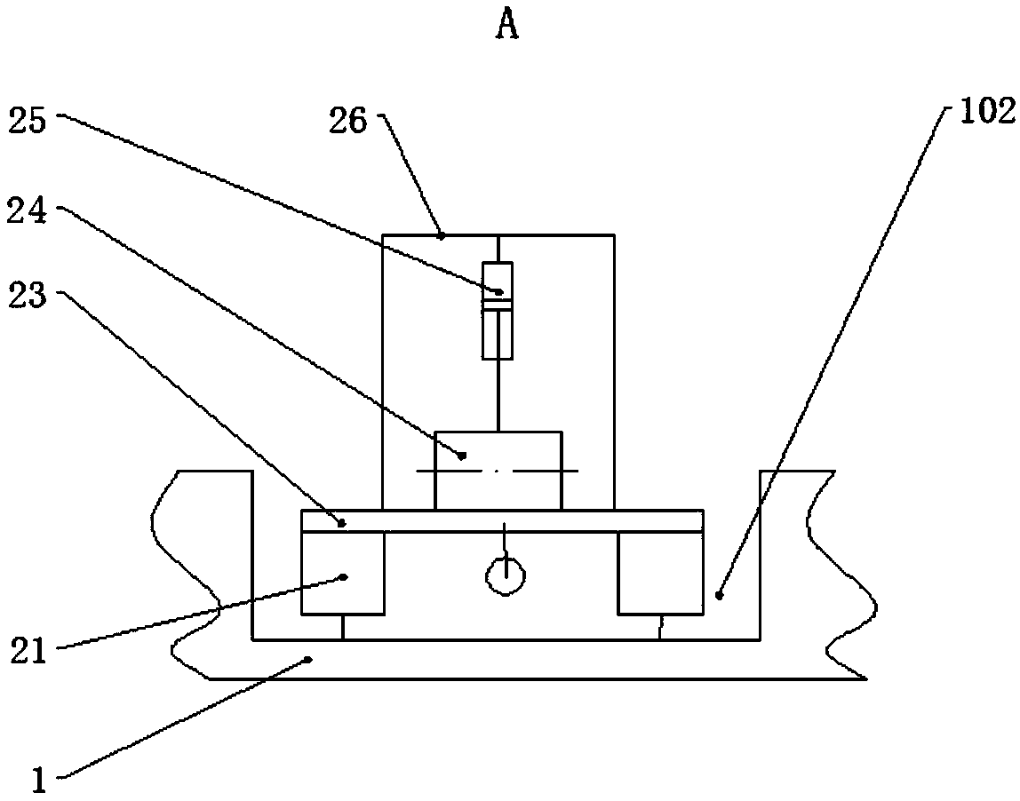
[0044] This embodiment relates to another preferred embodiment of the present invention, in particular to a pneumatically driven data binding machine, such as Figure 5-8 As shown, the document binding machine includes a paper storage box, a paper picking device, a finishing device, a binding device and a base 1 .

[0045] The bottom plate 101 of the base 1 is provided with a paper storage box, and the paper storage box is a grid area composed of partitions 102 for accommodating paper 2. According to the number of pages of each document, multiple paper storage boxes can be set. box.

[0046] A control platform 4 fixed on the base 1 is arranged above the paper storage box, four vacuum suction cups 5 for absorbing paper 2 are arranged on the control platform 4, and a first driving device for driving the vacuum suction cups 5 is arranged. The first driving device drives the vacuum chuck 5 to move horizontally and up and down between each paper storage box and the sorting area. ...


PUM


Abstract

The invention discloses a material binding machine. The material binding machine comprises a plurality of paper storage boxes, a paper taking device, a tidying device, a binding device and a base, wherein the plurality of the paper storage boxes are used for storing paper to be bound; the paper taking device is used for taking the paper out from each paper storage box and feeding the paper to a tidying area; the tidying device is used for tidying a whole document in sequence for binding; the binding device is used for binding the tidied paper; the base is used for supporting the devices, and provides the paper storage boxes and the tidying area through a bottom plate thereof. According to the material binding machine disclosed by the invention, a plurality of pages of documents are tidiedinto a whole document in sequence automatically according to setting, and is collected into an accommodating device through overturning after being bound, so that the labour intensity is greatly reduced, the work efficiency is improved, and the paper can also be prevented from being folded or damaged because of unbalance of an adsorption position. The material binding machine disclosed by the invention is simple in structure, reliable in action, suitable for various places, such as material tidying, file tidying and book tidying, and wide in application.

Description

technical field [0001] The invention belongs to the technical field of office appliances, and in particular relates to a document binding machine. Background technique [0002] In people's daily office process, the stapler is one of the indispensable tools and plays an important role. However, materials, books, test papers, magazines, etc. are often composed of multiple pages into a complete set of documents, which need to be printed in multiple copies. After each page of materials is printed, the printing workers basically manually organize them into a set of documents and then bind them together. This work is not only simple and boring, but also requires a lot of manpower, and the work efficiency is very low. Contents of the invention [0003] In order to solve the problems in the prior art that many pages of materials need to be sorted and bound after printing, and the work efficiency is low, the present invention provides a data binding machine, which can automaticall...

Claims


Application Information

Patent Timeline
Patent Type & Authority Applications(China)
IPC IPC(8): B42C1/12
Inventor 刘浏陈瑞燕
Owner JIANGSU UNIV OF TECH
Why Eureka
Try Eureka