
Mower

A lawnmower and machine body technology, applied in the field of weeding machinery, can solve problems such as insufficient suction

Active Publication Date: 2013-09-11
NINGBO LANGHUI TOOLS CO LTD
View PDF8 Cites 11 Cited by
  • Summary
  • Abstract
  • Description
  • Claims
  • Application Information

AI Technical Summary

Problems solved by technology

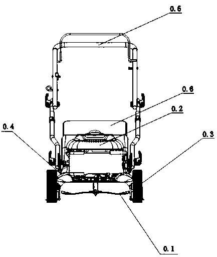
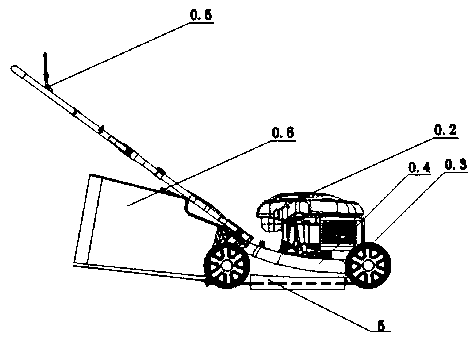
The engine 0.2 of the weeder is installed on the body 0.4 of the lawnmower, the output shaft of the engine 0.2 is connected with the blade 0.1, and the blade 0.1 utilizes the high-speed rotation of the engine 0.2 to trim the lawn, because the weeder needs to be moved, so mowing There is a certain distance between the machine body 0.4 and the ground. When weeding with the weeder, the weeder is moved, and the weeds enter the bottom of the weeder from the bottom of the front end of the weeder body 0.4. At the same time, the engine 0.2 drives the blade when it is working. The high-speed rotation of 0.1 interrupts the excessively high weeds, and at the same time, the upward airflow formed by the rotation of the blade at a height of 0.1 sucks up the grass blades that are partially interrupted by the blade 0.1. The problems existing in the weeder of the prior art are: There is a certain distance between the lawn mower body 0.4 and the ground, and the suction force caused by the rotation of the blade 0.1 driven by the engine 0.2 is insufficient, resulting in that many leaves and weeds under the blade 0.1 cannot be collected by the collecting device 0.6

Method used


Image

  • Mower
  • Mower
  • Mower

Examples


Embodiment Construction

[0016] Attached below figure 1 , 2 And attached image 3 Embodiments of the present invention are further described.

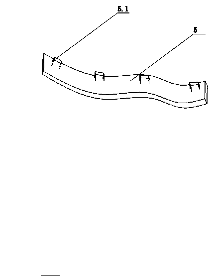
[0017] as attached figure 1 , 2 , 3 and 4, the prior art weeder comprises a blade 0.1, a motor 0.2 and a mower body 0.3, the motor 0.2 is installed on the mower body 0.3, and the output shaft of the motor 0.2 is in phase with the blade 0.1 Connection; when the engine 0.2 is working, it can drive the blade 0.1 to rotate, so as to achieve the effect of trimming the weeds, but at the same time, due to the large gap between the body 0.3 of the weeder and the ground, many weeds will be interrupted. But when interrupting, the wind force caused by the rotation of blade 0.1 is not enough, so that a lot of weeds will fall on the ground; and a kind of baffle piece made of flexible material that adopts in the present invention is attached on the lawn mower and has reached enhancement. The blade-suction function of the fan of the lawnmower itself is a lawnmower, whic...


PUM


Abstract

The invention aims to provide a device with a leaf sucking function on a mower, and discloses a mower. The technical scheme includes that the mower comprises a mower body (1), an engine (2) and blades (3), the engine (2) is fixed onto the mower body (1), and a rotary shaft of the engine (2) is connected with the blades (3). The mower is characterized by further comprising a first block piece (4) and a second block piece (5), the first block piece (4) and the second block piece (5) are made of flexible materials and are used for blocking a gap formed by the mower body (1) and the ground, the first block piece (4) is connected with the left side wall of the mower body (1), and the second block piece (5) is connected with the right side wall of the mower body.

Description

technical field [0001] The invention relates to a weeding machine, in particular to a lawnmower. Background technique [0002] Weeder is also called lawn machine or lawn trimmer, figure 1 Be the structure of the weeder of prior art, it comprises blade 0.1, motor 0.2, road wheel 0.3, mower body 0.4, handrail 0.5 and collecting device 0.6 to form. The engine 0.2 of the weeder is installed on the body 0.4 of the lawnmower, the output shaft of the engine 0.2 is connected with the blade 0.1, and the blade 0.1 utilizes the high-speed rotation of the engine 0.2 to trim the lawn, because the weeder needs to be moved, so mowing There is a certain distance between the machine body 0.4 and the ground. When weeding with the weeder, the weeder is moved, and the weeds enter the bottom of the weeder from the bottom of the front end of the weeder body 0.4. At the same time, the engine 0.2 drives the blade when it is working. The high-speed rotation of 0.1 interrupts the excessively high w...

Claims


Application Information

Patent Timeline
Patent Type & Authority Applications(China)
IPC IPC(8): A01D43/063
Inventor 赵延辉
Owner NINGBO LANGHUI TOOLS CO LTD
Learn More