
Closed circulation system for sealing and collecting oil fog of generator

A circulatory system and generator technology, applied in the direction of engine lubrication, hydropower, engine components, etc., can solve problems such as discount of oil mist collector effect, or improper maintenance, unreasonable selection, etc., to prevent pollution of generators. and the effect of the surrounding environment

Inactive Publication Date: 2014-01-01
DONGFANG ELECTRIC MACHINERY
View PDF8 Cites 3 Cited by
  • Summary
  • Abstract
  • Description
  • Claims
  • Application Information

AI Technical Summary

Problems solved by technology

[0006] Due to the lack of principle and structure of the oil mist collector, unreasonable type selection or improper maintenance, etc., the effect of the oil mist collector is greatly reduced, and there is still a certain amount of oil mist in the exhaust gas. For those with a large amount of oil mist Units, even the presence of a large amount of oil mist in the exhaust gas of the oil mist collector can be observed with the naked eye

Method used


Image

  • Closed circulation system for sealing and collecting oil fog of generator
  • Closed circulation system for sealing and collecting oil fog of generator

Examples


Embodiment 1

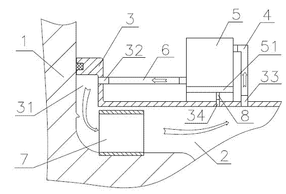
[0028] As the best embodiment of the present invention, with reference to the attached figure 2 A sealing cover 3 is arranged on the upper part of the oil tank 2, an annular cavity 31 is arranged on the upper part of the sealing cover 3, and one or several air inlet holes 32 are arranged on the inner surface of the annular cavity 31, and one or several exhaust holes 33 are arranged on the plane of the sealing cover And the oil return hole 34, the exhaust hole 33 is connected with the oil mist collector 5 through the oil mist pipe 4, the oil mist collector 5 is directly placed on the sealing cover or the oil tank cover, the outlet of the oil mist collector is connected to the exhaust gas discharge pipe 6 The sealing cover is connected to the air inlet 32, and the oil condensed by the oil mist collector is stored in the oil collection tank 51. The oil collection tank 51 is connected to the oil return hole 34 through the oil return pipe 8, and a check valve is installed on the oi...

Embodiment 2

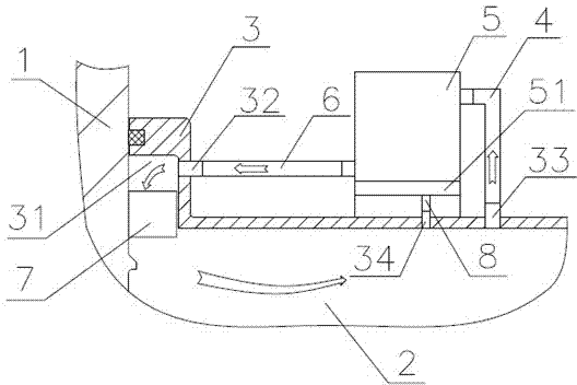
[0034] As another preferred embodiment of the present invention, refer to figure 1 , which includes the rotating parts of the thrust bearing or guide bearing of the generator, the oil tank surrounding the rotating parts, the upper part of the oil tank is provided with a sealing cover, and the sealing structure provided between the sealing cover and the rotating parts isolates the oil tank from the outside world, and the sealing structure can be Contact seal structure, gap seal structure, seal seal structure or comb-tooth seal structure, the seal cover is respectively opened with an air intake hole, an exhaust hole and an oil return hole communicating with the oil tank, and the rotating parts A fan is provided on the top to guide the airflow from the air inlet to the exhaust hole. The fan is located between the rotating part and the sealing cover. An oil mist collector is arranged on the sealing cover or the cover of the oil tank. The oil mist collector absorbs the oil mist The...


PUM


Abstract

The invention discloses a closed circulation system for sealing and collecting oil fog of a generator. The closed circulation system comprises a rotatable part of a generator thrust bearing or a guide bearing and an oil groove for surrounding the rotatable part, wherein the upper part of the oil groove is provided with a sealing cover, and a sealing structure arranged between the sealing cover and the rotatable part is used for isolating the oil groove and the outside; the sealing cover is respectively provided with an air inlet, an exhaust hole and an oil return hole communicated with the oil groove, the rotatable part of the generator is provided with a fan, and the sealing cover or an oil groove cover is provided with an oil fog collector; the oil fog collector is communicated with the exhaust hole through an oil-taking fog pipe, the outlet of the oil fog collector is communicated with the air inlet, and an oil liquid agglutinated by the oil fog collector is inputted into the oil return hole through an oil return pipe. The closed circulation system provided by the invention has the advantages that the oil fog is limited in a space formed by the oil groove, the oil fog collector and the oil-taking fog pipe, the oil fog is agglutinated by the oil fog collector into a liquid state to reflow in the oil groove, so that the sealing and collection of the oil fog are realized, and an overflowing problem of the oil fog is solved.

Description

[0001] technical field [0002] The invention relates to the technical field of oil mist sealing and collecting systems for generators. Background technique [0003] Generator bearings generally adopt sliding bearings, and the bearing pads are soaked in lubricating oil. When the unit rotates, on the one hand, the lubricating oil stirs and collides in the oil tank, generating a large number of bubbles, which burst to form oil mist; Therefore, the generation of oil mist is inevitable, and with the increase of the speed of the unit, or the increase of the line speed of the rotating parts at the tile surface of the unit, the severity of the oil mist will increase. During the operation of the unit, the oil mist accumulates continuously, the oil mist concentration and gas pressure in the oil tank increase, and the oil mist will overflow from the sealing structure. The overflowing oil mist will pollute the generator and the environment. In very serious cases, it may cause a s...

Claims


Application Information

Patent Timeline
IPC IPC(8): F16N31/02F03B11/00
CPCY02E10/226Y02E10/20
Inventor 邓斌骆林崔永明朱顺才邹应冬
Owner DONGFANG ELECTRIC MACHINERY
Learn More