A device power supply hysteresis protection circuit

A technology for protecting circuits and power supplies, applied in electrical components, output power conversion devices, etc., can solve problems such as troublesome power supply of operational amplifiers or comparators, and achieve the effect of low cost and simple circuit

Active Publication Date: 2018-02-13
XIAMEN YAXON NETWORKS CO LTD
View PDF5 Cites 0 Cited by
  • Summary
  • Abstract
  • Description
  • Claims
  • Application Information

AI Technical Summary

Problems solved by technology

The traditional solution is to realize the hysteresis protection function by controlling the switch of the device power supply by forming a hysteresis comparator through an op amp. However, when the device power supply (such as: DCDC converter) is not working, the power supply of the op amp or comparator is troublesome. question

Method used


Image

  • A device power supply hysteresis protection circuit
  • A device power supply hysteresis protection circuit
  • A device power supply hysteresis protection circuit

Examples


Embodiment Construction

[0018] The present invention will now be further described with reference to the accompanying drawings and specific embodiments.

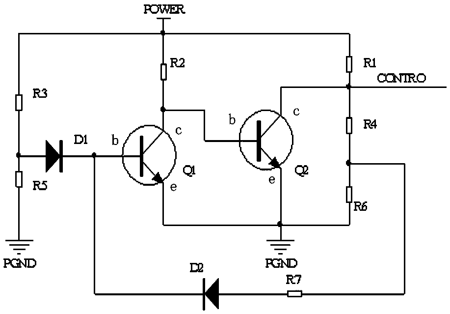
[0019] figure 1 Shown is the principle of the device power supply hysteresis protection circuit of the present invention, which is composed of resistors, diodes and triodes. The circuit diagram is as follows: two resistance voltage divider networks are connected in parallel between the positive pole POWER and the negative pole PGND of the power supply of the device. The four resistors R4 and the sixth resistor R6 are formed in series in sequence, and the positive pole POWER of the device power supply is also connected in series with a second resistor R2, which are respectively connected to the collector c of the first transistor Q1 and the base of the second transistor Q2. pole b, the emitters e of the first transistor Q1 and the second transistor Q2 are both connected to the negative pole PGND of the device power supply, and the middle terminals ...


PUM


Abstract

The invention relates to the field of electronic circuits. The equipment power supply hysteresis protection circuit is: two resistor divider networks are connected in parallel between the positive pole and the negative pole of the equipment power supply. The positive electrode of the equipment power supply is also connected in series with a resistor R2, which is respectively connected to the collector of the transistor Q1 and the base of the transistor Q2. The emitters of the transistor Q1 and the transistor Q2 are both connected to the negative electrode of the equipment power supply. The middle end of the resistor R5 is connected in series with a forwardly connected diode D1, and then connected to the base of the transistor Q1, the middle ends of the resistor R1 and the resistor R4 are connected to the collector of the transistor Q2, and the middle ends of the resistor R4 and the resistor R6 are connected in series A forward connected diode D2 is connected to the base of the triode Q1, and the collector of the triode Q2 is the output control terminal of the circuit to control the power on or off of the device. The invention realizes the hysteresis protection and undervoltage protection functions of the equipment power supply.

Description

technical field [0001] The invention relates to the field of electronic circuits, in particular to a control circuit of a power supply. Background technique [0002] When the power supply of the existing equipment fluctuates, due to the frequent switching of the power supply of the whole machine, the equipment resets, the power supply and the internal circuit are impacted, and the equipment is often damaged. Voltage shutdown protection (ie, turn off the battery power when the battery voltage is insufficient). Therefore, an effective means is required to prevent the occurrence of this problem. The traditional solution is to use an op amp to form a hysteresis comparator to control the switch of the device power supply to realize the hysteresis protection function. However, when the device power supply (such as a DCDC converter) is not yet working, the power supply of the op amp or the comparator is troublesome. question. SUMMARY OF THE INVENTION [0003] Therefore, the pr...

Claims


Application Information

Patent Timeline
Patent Type & Authority Patents(China)
IPC IPC(8): H02M1/32
Inventor 叶志聪蔡运文吴振达肖振隆蔡炎平
Owner XIAMEN YAXON NETWORKS CO LTD
Why Eureka
Try Eureka