
Reusable DC Ice Melting Device

A DC ice melting, DC side technology, applied in the direction of converting irreversible AC power input to DC power output, harmonic reduction device, AC network to reduce harmonic/ripple, etc., can solve the problem of high cost of large capacity ice melting device , limited output voltage regulation ability, low power factor and other problems, to achieve the effect of improving power quality, increasing utilization, and low cost

Active Publication Date: 2017-09-08
STATE GRID HUNAN ELECTRIC POWER +3
View PDF6 Cites 0 Cited by
  • Summary
  • Abstract
  • Description
  • Claims
  • Application Information

AI Technical Summary

Problems solved by technology

Diode uncontrolled rectification has the advantages of simple structure, no need for control devices, small loss of switching devices, and low cost, but its output voltage adjustment capability is limited, and it only starts to operate during ice disasters, and its utilization rate is low; based on uncontrollable thyristors The rectifier can adjust the rectified output voltage by changing the firing angle of the thyristor, but the harmonics generated by the device are large and the power factor is low
The fully-controlled rectification device based on IGBT can realize smooth adjustment of output voltage, and can realize rectification without harmonics and high power factor, and the performance of the device is superior; but the large-capacity ice-melting device with this structure is expensive

Method used


Image

  • Reusable DC Ice Melting Device
  • Reusable DC Ice Melting Device

Examples


Embodiment Construction

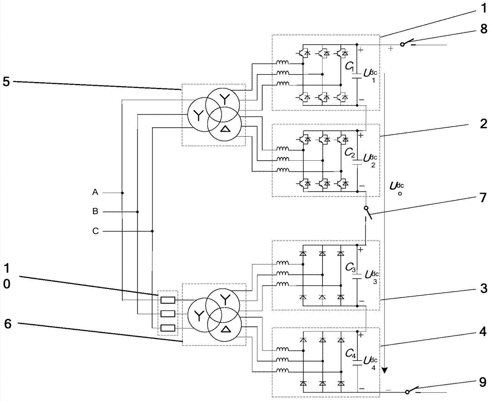
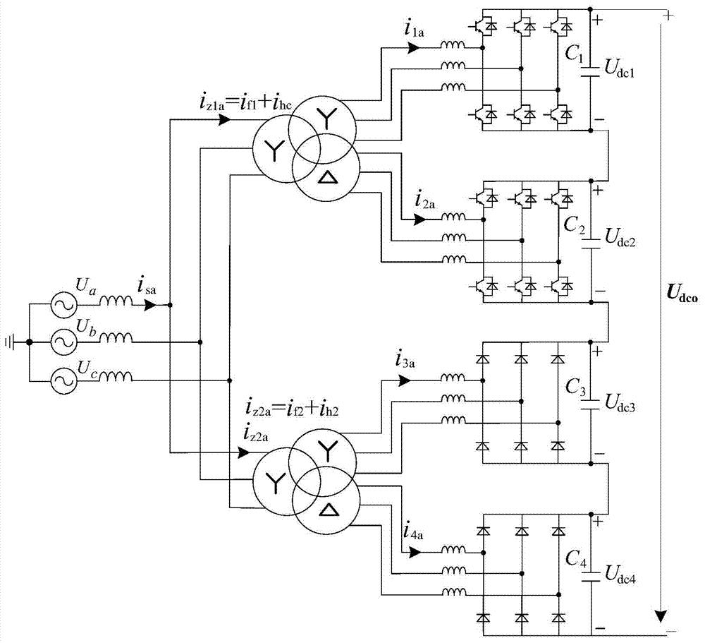
[0026] See attached figure 1 , figure 1 Shown is one embodiment of the reusable direct current ice melting device of the present invention. The connection between the first fully-controlled PWM rectifier 1 and the second fully-controlled pulse-width modulated rectifier 2 in this embodiment is a commercially available SG1000TS-MV rectifier produced by China Anhui Sunshine Power Supply Co., Ltd. The first uncontrollable rectifier 3 and the second uncontrollable rectifier 4 are ZZR-8 rectifiers produced by China Hunan Xiangdian Trial Technology Co., Ltd. The first three-winding rectifier transformer 5 and the second three-winding rectifier transformer 6 adopt the ZSS-20M / 10 three-winding rectifier transformer developed by China TBEA Hengyang Transformer Co., Ltd. Electric Branch. The first single-phase isolating switch 7 , the second single-phase isolating switch 8 , and the third single-phase isolating switch 9 are GWDCD1-12 single-phase isolating switches produced by China Zh...


PUM


Abstract

The invention discloses a reusable direct-current ice melting device which is formed by connecting a first full-controlled pulse width modulation rectifier (1), a second full-controlled pulse width modulation rectifier (2), a first uncontrollable rectifier (3), a second uncontrollable rectifier (4), a first three-winding rectifier transformer (5), a second three-winding rectifier transformer (6), a first single-phase isolating switch (7), a second single-phase isolating switch (8), a third single-phase isolating switch (9) and a three-phase circuit breaker (10). The device has the advantages that (1) the voltage can be continuously regulated in a direct-current ice melting mode, the device can operate in an electric energy quality regulation mode when an electric transmission line is not covered by ice, the electric energy quality is improved, and the utilization rate is improved; (2) the cost is greatly reduced; (3) the ice melting requirements of electric transmission lines of different lengths and different currents can be met; (4) the reusable direct-current ice melting device has the advantages of low cost and high performance.

Description

technical field [0001] The invention relates to an ice-melting device, in particular to a reusable direct current ice-melting device. Background technique [0002] Icing of power grid lines poses a serious threat to the safe and stable operation of the power grid. This resulted in downed towers and broken lines, large-scale power outages, and even partial power grids being paralyzed. Therefore, in recent years, power grid ice disaster prevention has become the focus of power industry research. [0003] The AC short-circuit ice melting technology has the disadvantages of large capacity required for ice melting power supply, large reactive power demand for the system, and difficult matching of line impedance. DC short circuit ice melting technology is currently the most effective means to resist icing of power grid lines. Since the DC impedance of the line inductance is negligible, the required capacity of the DC short-circuit deicing power supply is much smaller than that ...

Claims


Application Information

Patent Timeline
Patent Type & Authority Patents(China)
IPC IPC(8): H02M7/40H02J3/01
CPCY02E40/40
Inventor 陆佳政吴传平张红先李波方针赵纯
Owner STATE GRID HUNAN ELECTRIC POWER
Learn More