
Denoising radio frequency spectrum peak value acquisition method based on Internet of things electric power temperature measurement equipment

A power temperature measurement and noise removal technology, which is applied in transmission noise suppression, network planning, electrical components, etc., can solve problems such as wrong judgment of radio frequency spectrum peaks, and achieve the effect of avoiding interference, huge economic losses and casualties

Active Publication Date: 2014-01-01
TIANJIN 712 COMM & BROADCASTING CO LTD +1
View PDF4 Cites 9 Cited by
  • Summary
  • Abstract
  • Description
  • Claims
  • Application Information

AI Technical Summary

Problems solved by technology

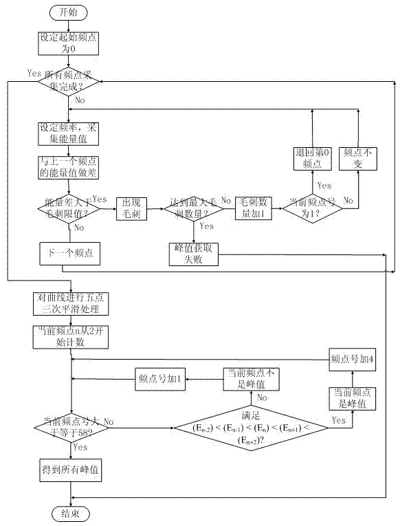
This method is applied to the power temperature measurement equipment of the Internet of Things. By sequentially removing the burrs and protrusions in the radio frequency spectrum curve, it can effectively eliminate the influence of the common environmental noise in the radio frequency system on the radio frequency equipment, and can effectively solve the problem of radio frequency under the influence of environmental noise. The problem of wrong judgment of spectrum peak

Method used


Image

  • Denoising radio frequency spectrum peak value acquisition method based on Internet of things electric power temperature measurement equipment
  • Denoising radio frequency spectrum peak value acquisition method based on Internet of things electric power temperature measurement equipment
  • Denoising radio frequency spectrum peak value acquisition method based on Internet of things electric power temperature measurement equipment

Examples


Embodiment Construction

[0017] The present invention will be further described below with reference to the accompanying drawings and examples: In the measurement process of the electric temperature measuring equipment, it is necessary to obtain the response frequency point of the tag. First, the tag bandwidth is divided into several frequency points on average, and the "frequency-energy" curve (spectrum curve) of the tag is drawn by measuring the energy value corresponding to each frequency point. By analyzing the curve, find all the peaks in the curve, and find the peak with the largest amplitude from all the peaks, that is, the peak-to-peak value, so as to obtain the frequency point with the largest energy as the response frequency point of the tag.

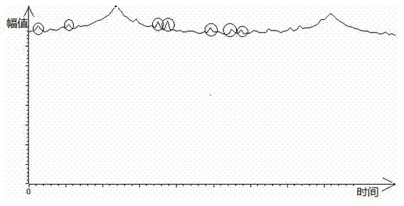
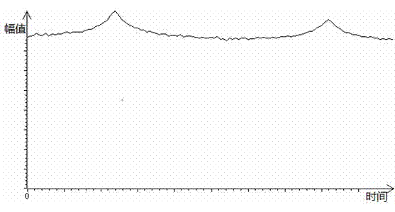
[0018] The measured original spectrum curve is as figure 2 shown. It can be seen that due to environmental noise interference and other reasons, there are some glitches (circled parts on the curve) in the spectrum curve. The energy value of the gli...


PUM


Abstract

The invention relates to a denoising radio frequency spectrum peak value acquisition method based on Internet of things electric power temperature measurement equipment. The denoising radio frequency spectrum peak value acquisition method based on the Internet-of-things electric power temperature measurement equipment comprises the steps of firstly, measuring and collecting the echo energy values of all frequency points within a label band width range, and re-measuring a frequency point if burr occurs suddenly in the measurement process so as to achieve the aim of eliminating the burr; then eliminating smaller bulges in a frequency spectrum curve line by a smoothing algorithm, and reducing the amplitude of a larger bulge in the curve line; and finally, acquiring all peak values in the curve line accurately by a five-point peak value judgment method. By adopting the method, the influences on the temperature measurement equipment caused by the interference of the same-frequency-band radio frequency equipment, environment noise and measurement errors are effectively avoided, further, the frequency spectrum curve peak can be acquired correctly, and finally temperature can be measured correctly. The real-time monitoring on equipment in running is realized by utilizing an SAW-RFID (surface acoustic wave-radio frequency identification device), so that electric power operation departments can forecast the failure and can solve problems in advance, and a large amount of economical loss and injuries and deaths of people in failure are prevented.

Description

technical field [0001] The invention relates to a digital signal processing method for temperature measurement of power system-related equipment using surface acoustic wave radio frequency identification technology (SAW-RFID) in the Internet of Things, in particular to a denoising method for power temperature measurement equipment based on the Internet of Things Method for obtaining peak value of radio frequency spectrum. Background technique [0002] With the in-depth development of the Internet of Things technology, item management and equipment operation monitoring have become important front-end technologies of the Internet of Things. The use of SAW-RFID to realize constant monitoring of equipment operation can enable the power operation department to predict failures and solve problems in advance, avoiding huge economic losses and casualties caused by failures. [0003] The principle of using SAW-RFID temperature measuring equipment for temperature measurement is: as t...

Claims


Application Information

Patent Timeline
Patent Type & Authority Applications(China)
IPC IPC(8): H04B15/00H04W16/14H04L29/08
CPCY02B60/50
Inventor 李鸿儒吴昊王飞
Owner TIANJIN 712 COMM & BROADCASTING CO LTD
Learn More