Pump for dispensing a fluid material

A fluid product, dispensing pump technology, used in jet devices, inhalers, individual handheld devices, etc., to solve problems such as natural deformation and increased pressure drop in reservoirs

Inactive Publication Date: 2014-01-01
APTAR FRANCE SAS
View PDF6 Cites 9 Cited by
  • Summary
  • Abstract
  • Description
  • Claims
  • Application Information

AI Technical Summary

Problems solved by technology

However, as the pump is used, some of the pump components, usually made of substantially rigid plastic material, are at risk of naturally deforming under the pr

Method used


Image

  • Pump for dispensing a fluid material
  • Pump for dispensing a fluid material
  • Pump for dispensing a fluid material

Examples


Embodiment Construction

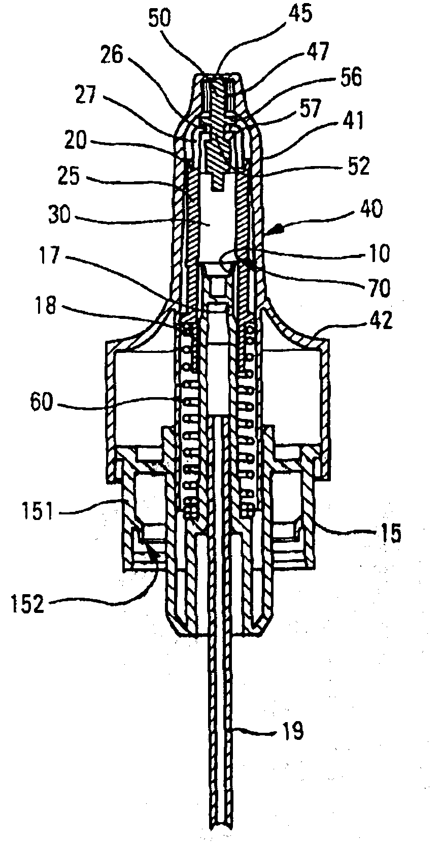
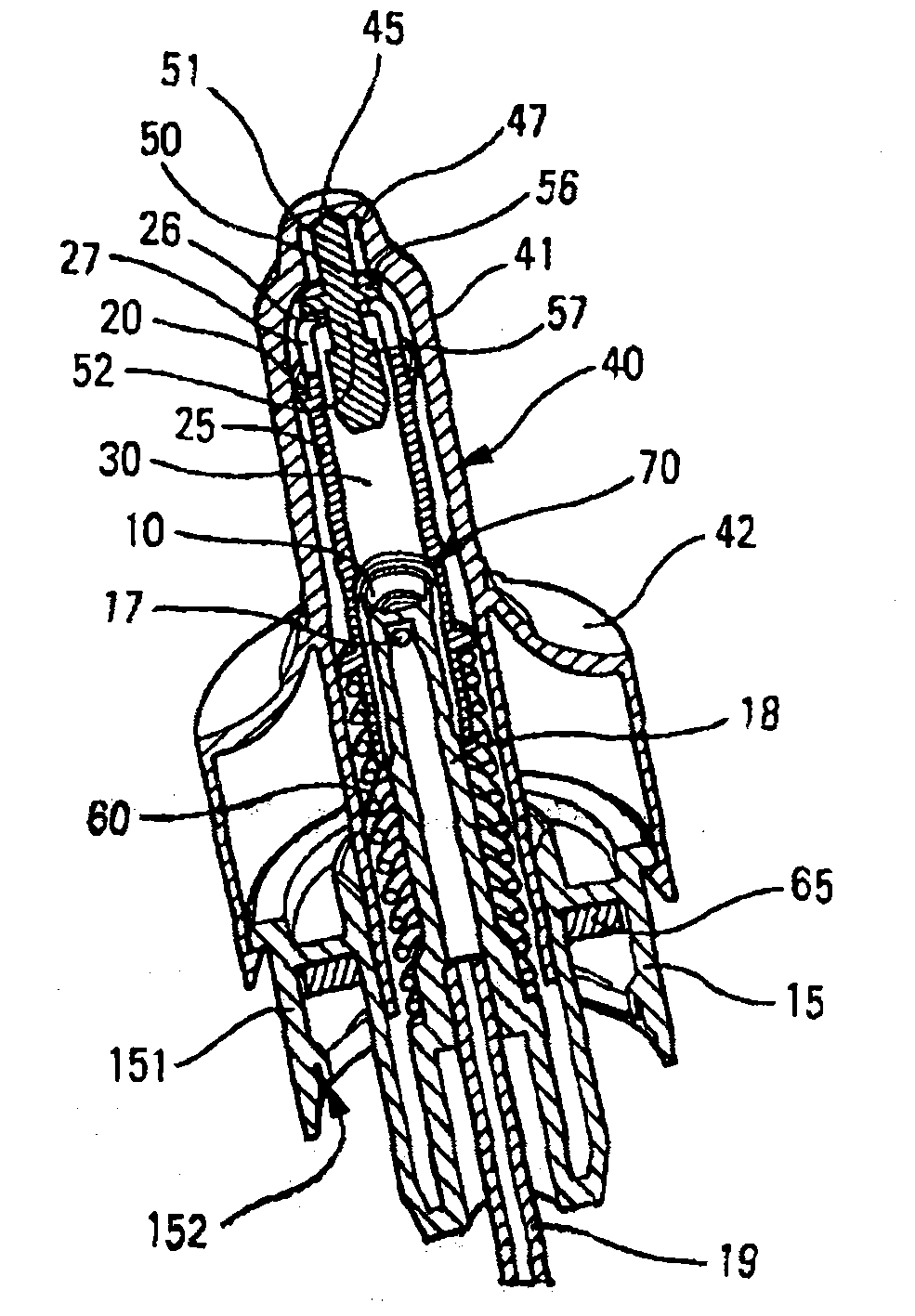
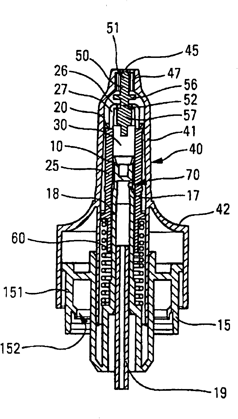
[0028] With reference to the figures, the fluid product dispensing device comprises a dispensing pump mounted on a reservoir (not shown) by means of a retaining ring 15 , advantageously interposed with a sealing gasket 65 . This retaining ring can be a crimp, twist or snap ring. A dispensing head 40 comprising a dispensing orifice 45 is provided for actuating said pump 10 . As shown in the drawings, the dispensing head may be a nose-shaped head with an elongated axial portion 41 intended to be inserted into the user's nostril, and the dispensing orifice is located in said elongated portion of the dispensing head. The downstream end of the long axial portion. A widened actuation portion 42 is provided for allowing the user to depress the dispense head with his finger to actuate the pump. Advantageously, the dispensing orifice is provided with a spray profile for dispensing the product in the form of a finely sprayed spray.

[0029] The dispensing pump comprises a first pisto...


PUM


Abstract

A fluid dispenser pump including a first piston, a second piston, and a dispenser head with a dispenser orifice, for actuating the pump, a shutter arranged upstream from the dispenser orifice, the shutter movable between closed and open positions. The second piston is formed outside a hollow part and is slidable inside the dispenser head. The first piston is slidable inside the hollow part, the hollow part including an axial opening defined by a radial edge through which passes a stem portion of the shutter. The stem portion is between a proximal radial shoulder and a distal radial shoulder of the shutter, the shutter being moved from its closed position to its open position by the radial edge of the hollow part co-operating with the distal radial shoulder, and being moved from its open position to its closed position by the radial edge co-operating with the proximal radial shoulder.

Description

technical field [0001] The present invention relates to a fluid dispensing pump and a fluid dispensing device comprising such a pump. Background technique [0002] Fluid dispensing pumps are well known in the prior art, especially for dispensing fluid, liquid or paste products in the cosmetic, perfumery or pharmaceutical fields. Fluid dispensing pumps generally comprise a piston sliding within a pump body, more particularly in a pump chamber provided therein, adapted to dispense a dose of fluid each time the pump is actuated. The pump chamber typically includes an inlet valve to allow determination of the dose of product expelled on each actuation. In addition, especially for pharmaceutical products, some pumps sometimes include a closure at the dispensing orifice to avoid any contamination of the product between actuations. [0003] A problem that arises with this type of pump involves triggering. In fact, before the pump is actuated for the first time, the pump chamber ...

Claims


Application Information

Patent Timeline
IPC IPC(8): B05B11/00A61M15/08
CPCA61M15/08B05B11/3047B05B11/3016B05B11/3001B05B11/3004B05B11/3094B05B11/3074B05B11/3063B05B11/304B05B11/1016B05B11/104B05B11/1047B05B11/1063B05B11/1074B05B11/1094B05B11/1004B05B11/1001
Inventor L·珀蒂
Owner APTAR FRANCE SAS
Why Eureka
Try Eureka