Shoe airing rack

A shoe and clothes rail technology, applied in the field of shoe racks, can solve problems such as inconvenient drying, and achieve good application prospects, easy implementation, and simple structure

Inactive Publication Date: 2014-01-08
蔡卫进
View PDF0 Cites 1 Cited by
  • Summary
  • Abstract
  • Description
  • Claims
  • Application Information

AI Technical Summary

Problems solved by technology

[0003] The technical problem solved by the present invention is to overcome the problem of drying shoes in the prior art, which is basically placed on a horizontal surface and is inconvenient to dry.

Method used


Image

  • Shoe airing rack

Examples


Embodiment Construction

[0009] The present invention will be further described below in conjunction with the accompanying drawings.

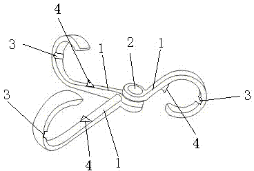
[0010] Such as figure 1 As shown, a shoe drying rack includes three hook bodies 1, and the three hook bodies 1 are connected by movable rotating shafts 2. The top of the inner wall of each hook body 1 is provided with a groove 3 for clamping a clothes rail , to prevent the shoe rack from falling off. When in use, one of the hook bodies 1 is placed on the clothes rail, and the other two hook bodies 1 are used to hang the shoes. The degree of comparison between the shoes can be obtained by rotating the hook body 1, which is convenient to use , the inner wall of each hook body 1 is also provided with a barb 4 for preventing shoes from falling off, and the barb 4 can block the shoes placed on it, the structure is simple, and the drying effect is good.

[0011] To sum up, the shoe drying rack of the present invention can hang shoes on the hooks, the angle between the hooks...


PUM


Abstract

The invention discloses a shoe airing rack. The shoe airing rack comprises three hook bodies, the three hook bodies are connected through a movable revolving shaft, the top of the inner wall of each hook body is provided with a groove for clamping a clothes airing rod, and the inner wall of each hook body is further provided with a reverse hook for preventing a shoe from falling off. According to the shoe airing rack, the shoes can be placed on the hooks, the angles between the hooks can be adjusted freely, and therefore the shoe airing rack is convenient to use, good in shoe airing effect, simple in structure and easy to achieve and has a good application prospect.

Description

technical field [0001] The invention relates to a shoe drying rack, which belongs to daily necessities. Background technique [0002] At present, when people are drying shoes, they are basically placed on a horizontal plane, which is inconvenient to dry. Contents of the invention [0003] The technical problem solved by the present invention is to overcome the problem that drying shoes in the prior art is basically placed on a horizontal surface and is inconvenient to dry. [0004] In order to solve the problems of the technologies described above, the technical solution adopted in the present invention is: [0005] A shoe drying rack, which is characterized in that it includes three hook bodies, which are connected by movable rotating shafts, and the top of the inner wall of each hook body is provided with a groove for clamping a clothes drying rod. [0006] The aforementioned shoe drying rack is characterized in that: the inner wall of each hook body is also provided w...

Claims


Application Information

Patent Timeline
IPC IPC(8): A47G25/00
Inventor 蔡卫进
Owner 蔡卫进
Why Eureka
Try Eureka