Garbage compressor

A technology for garbage compressors and garbage, which is applied in presses, manufacturing tools, etc. It can solve problems such as short strokes, secondary pollution, and garbage entrained in guide rails, so as to increase the contact area, prevent secondary dust and odor, Easy to clean and maintain

Active Publication Date: 2015-06-10
广西玉柴专用汽车有限公司
View PDF8 Cites 0 Cited by
  • Summary
  • Abstract
  • Description
  • Claims
  • Application Information

AI Technical Summary

Problems solved by technology

[0004] In order to overcome the defects of the prior art, the present invention invents a garbage compressor, which has a short stroke and effectively solves the problems of guide rails entraining garbage and secondary pollution during the compression process.

Method used


Image

  • Garbage compressor
  • Garbage compressor
  • Garbage compressor

Examples


Embodiment

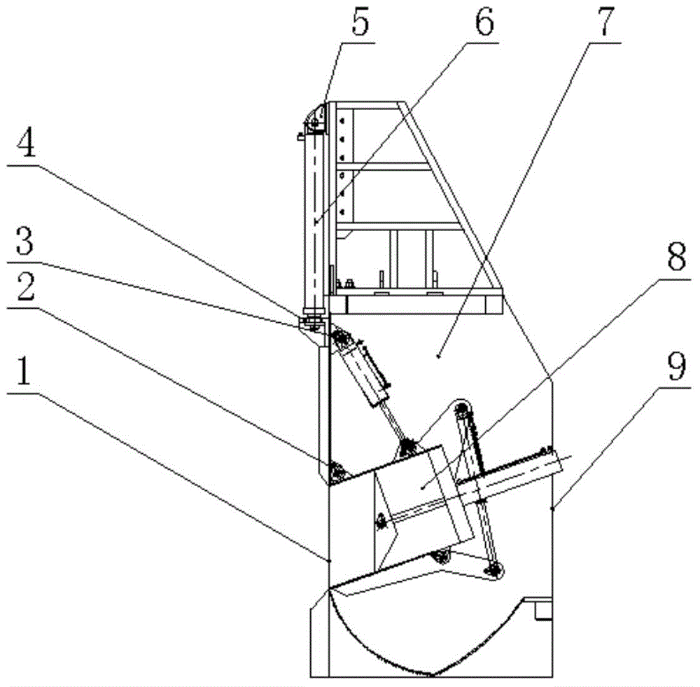
[0045] A trash compactor such as figure 1 As shown, it includes: a body 7, a gate oil cylinder support 5, a gate oil cylinder 6, a docking mechanism 4 and a compression mechanism 8, wherein the gate oil cylinder support 5 is fixedly installed on the upper end of the side of the body 7 where the garbage outlet 1 is located, and the gate oil cylinder 6 cylinders The tail end of the body is fixedly connected to the gate oil cylinder support 5, the head of the piston rod of the gate oil cylinder 6 is fixedly connected to the docking mechanism 4, and the inner side of the upper end of the garbage outlet 1 of the body 7 is provided with two first hinge seats 2 before and after. Two second hinge seats 3 are arranged above the hinge seat 2, and the compression mechanism 8 is integrally installed in the inner cavity of the body 7 through the two first hinge seats 2 and the second second hinge seats 3.

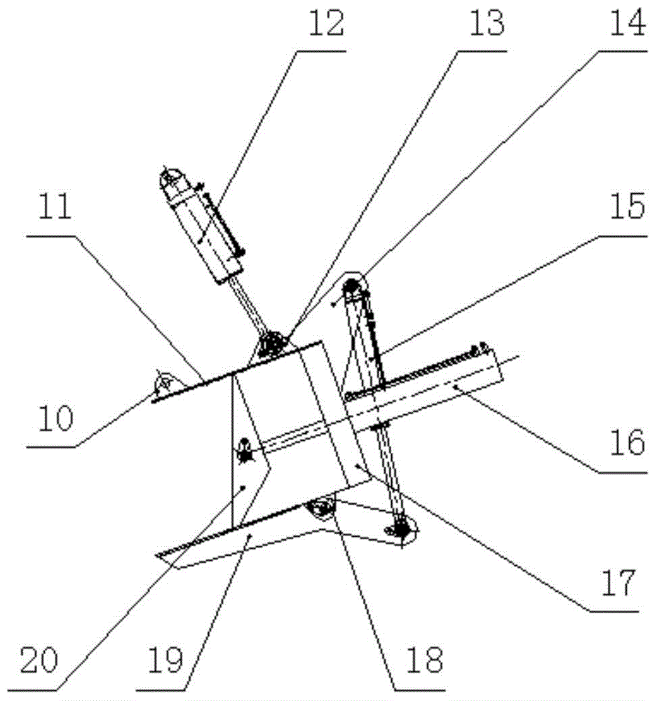
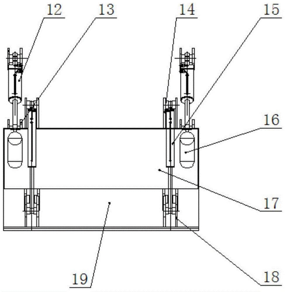
[0046] Such as figure 2 and image 3 As shown, the compression mechanism 8 inclu...


PUM


Abstract

The invention discloses a garbage compressor which comprises a machine body and a compressing mechanism installed in the machine body in a suspension mode. The machine body is provided with a garbage inlet, a garbage outlet and a gate mechanism. The compressing mechanism comprises a swinging plate, a first driving part, a baffle, a scraping plate, a second driving part, a push plate and a third driving part. The front end of the swinging plate is hinged to the inner wall of the upper end of the garbage outlet. The first driving part is arranged on the inner wall of the machine body and connected with the swinging plate to drive the swinging plate to swing around the front end. The upper end of the baffle is fixedly connected with the rear end of the swinging plate. The rear end of the scraping plate is hinged to the lower end of the baffle. The second driving part is arranged on the swinging plate and connected with the scraping plate to drive the front end of the scraping plate to rotate around the rear end of the scraping plate. The push plate is arranged below the swinging plate in a moving mode. The third driving part is arranged on the baffle and is connected with the push plate to drive the push plate to move. The garbage compressor can reduce the stroke of the driving parts and effectively solve the problems that secondary pollution occurs in a garbage compression process and a guide rail clamps garbage along with the guide rail.

Description

technical field [0001] The invention relates to a garbage disposal device, in particular to a garbage compressor. Background technique [0002] At present, municipal solid waste is transported and landfilled over long distances, and the volume of the waste needs to be reduced, and the waste compressor is the main equipment. The existing garbage compressors are mainly divided into two types, one of which is a vertical press-fitting type, which is inconvenient to load materials, and there will be odor, secondary dust, and secondary pollution; the other is a horizontal press-fitting type Type, the working stroke is long, and its guide rail is easy to entrain garbage, which will affect the operation of the equipment, and it is troublesome to clean and maintain. [0003] Therefore still be necessary to make further improvement to existing garbage compactor. Contents of the invention [0004] In order to overcome the defects of the prior art, the present invention invents a ga...

Claims


Application Information

Patent Timeline
Patent Type & Authority Patents(China)
IPC IPC(8): B30B9/30B30B15/00
Inventor 覃启华黄县媛罗文航殷俊廖向辉梁挺新孙玉文李燕
Owner 广西玉柴专用汽车有限公司
Why Eureka
Try Eureka