Projection device

A projection device and heat dissipation space technology, applied in projection devices, optics, instruments, etc., can solve the problems of increased fan speed and power, poor heat dissipation effect, etc., to achieve the effect of ensuring stability and avoiding heat scurry

Active Publication Date: 2014-01-08
QISDA OPTRONICS (SUZHOU) CO LTD +1
View PDF14 Cites 10 Cited by
  • Summary
  • Abstract
  • Description
  • Claims
  • Application Information

AI Technical Summary

Problems solved by technology

At present, in order to improve the heat dissipation effect of the projector, the industry usually increases the fan speed or adopts a high-power fan to enhance heat dissipation. However, the speed and power of the fan cannot be increased without limit, so the heat dissipation effect is not very good.

Method used


Image

  • Projection device
  • Projection device

Examples


Embodiment Construction

[0029] In order to have a further understanding of the purpose, structure, features, and functions of the present invention, the following detailed descriptions are provided in conjunction with the embodiments.

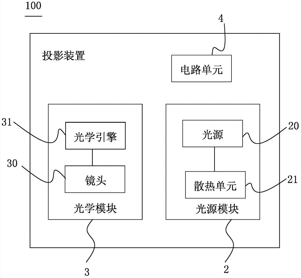
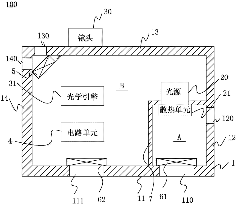
[0030] refer to figure 1 and figure 2 As shown, a schematic diagram of a projection device 100 of the present invention is disclosed. like figure 1 and figure 2 As shown, the projection device 100 of the present invention includes a housing 1 , a light source module 2 , an optical module 3 and a circuit unit 4 , wherein the housing 1 is used to accommodate the light source module 2 , the optical module 3 and the circuit unit 4 .

[0031] The casing 1 has a first heat dissipation space A and a second heat dissipation space B isolated from the first heat dissipation space A, wherein the casing includes a first side wall 11, a second side wall 12, a third side wall 13 and The fourth side wall 14, wherein the first side wall 11 is opposite to the third side wall 13,...


PUM


Abstract

The invention provides a projection device which comprises a shell, a light source module and a heat dissipation unit. The shell is provided with first heat dissipation space and second heat dissipation space isolated with the first heat dissipation space. The shell comprises a first side wall provided with a first air inlet, a second side wall provided with a first air outlet and adjacent to the first side wall, and a third side wall oppositely arranged with the first side wall. The light source module comprises a light source which is arranged in the second heat dissipation space. The heat dissipation unit is connected with the light source, used for guiding heat generated by the light source and arranged in the first heat dissipation space. The first air inlet and the first air outlet are connected with the first heat dissipation space. First heat dissipation airflow flows through the first heat dissipation space through the first air inlet and flows out of the shell through the first air outlet, and the first heat dissipation airflow flows through the heat dissipation unit.

Description

technical field [0001] The present invention relates to a projection device, in particular to a projection device which prevents electronic components in the heat dissipation space from overheating by designing a flow path. Background technique [0002] At present, daily life is full of various electronic devices, and electronic devices always have heat dissipation problems. When the heat dissipation is insufficient and the operating characteristics of electronic components are affected, not only the life of electronic components will be shortened, but the operation stability of the entire electronic device will also be affected. Will be affected, or even fail. Taking a projector as an example, its heat sources are mainly the light source and the driving circuit module, and among the two, the heat generated by the light source is the most, and the heat generated by the light source will also affect the driving circuit module, so that the driving circuit module can not only w...

Claims


Application Information

Patent Timeline
Patent Type & Authority Applications(China)
IPC IPC(8): G03B21/16
Inventor 刘玉婷林颖芳魏宏任
Owner QISDA OPTRONICS (SUZHOU) CO LTD
Why Eureka
Try Eureka