Die-casting formation mold for annular shell

A die-casting and ring-shaped technology, which is applied in the field of die-casting molding molds for ring-shaped shells, can solve problems such as unreasonable design of die-casting molds and poor quality of ring-shaped shells, so as to achieve smooth transportation, ensure molding quality, and prevent scurrying Effect

Pending Publication Date: 2018-05-04
CHANGCHANG DIE CASTING CO
View PDF0 Cites 2 Cited by
  • Summary
  • Abstract
  • Description
  • Claims
  • Application Information

AI Technical Summary

Problems solved by technology

[0004] At present, in the process of forming the annular shell by the existing die-casting mold, due to the unreasonable design of the die-casting mold, the quality of the formed annular shell is poor

Method used


Image

  • Die-casting formation mold for annular shell
  • Die-casting formation mold for annular shell
  • Die-casting formation mold for annular shell

Examples


Embodiment Construction

[0021] Embodiments of the present invention will now be described with reference to the drawings, in which like reference numerals represent like elements.

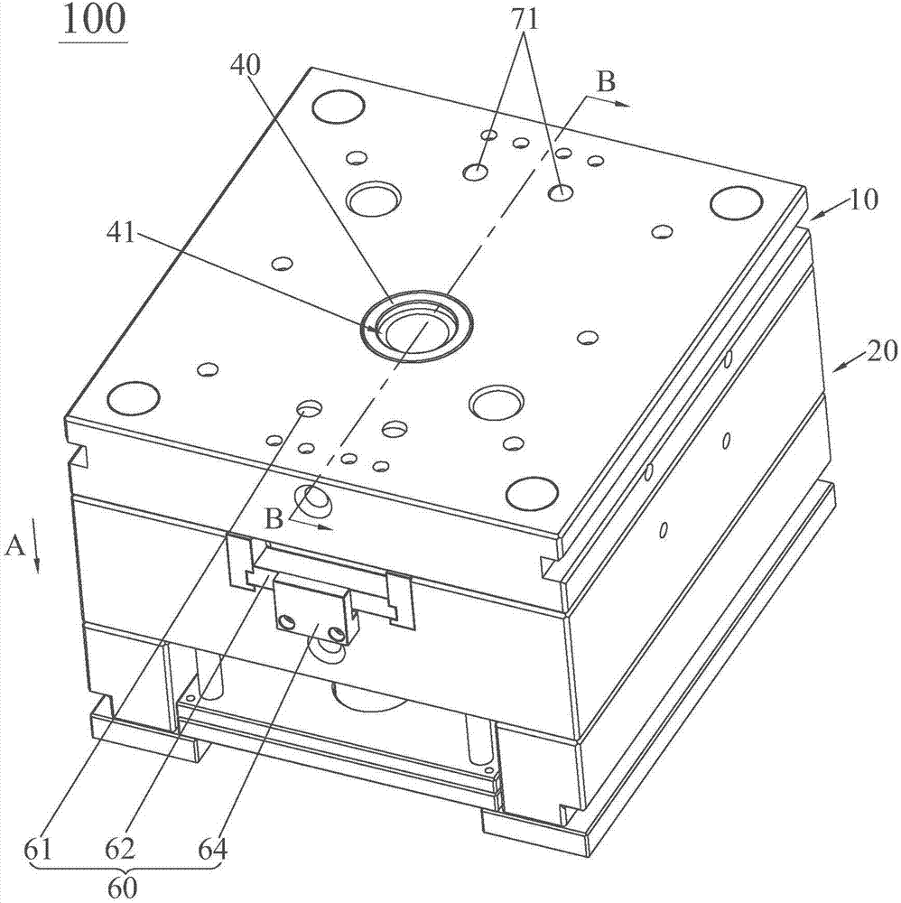
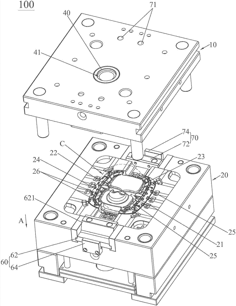
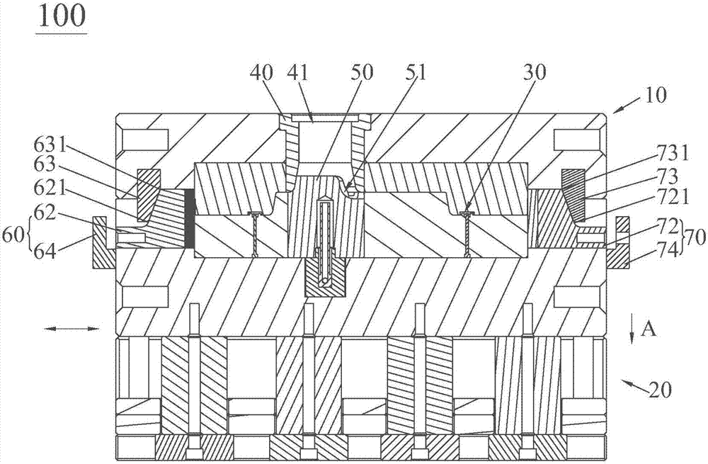
[0022] see Figure 1 to Figure 3 , the die-casting mold 100 for an annular shell of the present invention is used to form an end-to-end closed annular shell 200, including a pouring nozzle 40, a splitter cone 50, a left side pumping mechanism 60, a right side pumping mechanism 70, and fixed Die 10 and moving die 20. The fixed mold 10 and the movable mold 20 jointly enclose a ring cavity 30 closed end to end after the mold is closed. The pouring nozzle 40 and the splitter cone 50 are located in the space surrounded by the ring cavity 30. The pouring nozzle 40 is installed on the fixed mold 10. The splitter cone 50 is installed on the movable mold 20 and defines a splitter groove 51 connected with the sprue of the pouring nozzle 40 .

[0023] The left drawing mechanism 60 includes an oblique guide column 61 installed on t...


PUM


Abstract

The invention discloses a die-casting formation mold for an annular shell. The die-casting formation mold for the annular shell comprises a pouring nozzle, a sprue spreader, a left side drawing mechanism, a right side drawing mechanism, a fixed mold and a movable mold. The fixed mold and the movable mold are combined and then jointly define an annular cavity with the head and the tail being closed. The left side drawing mechanism and the right side drawing mechanism each comprise inclined guide columns, a side drawing sliding block and a side drawing lock block. Each side drawing lock block isprovided with a first inclined structure. Each side drawing sliding block is provided with a second inclined structure. The inclined guide columns of each side drawing mechanism are arranged in the corresponding side drawing sliding block in penetrating and sliding manners. The movable mold is provided with a first main groove, a second main groove, a first branch groove, a second branch groove,first communicating grooves and second communicating grooves. The first branch groove is arranged along the outline of the inner cavity wall on the front side of the annular cavity. The second branchgroove is arranged along the outline of the inner cavity wall on the back side of the annular cavity. The groove depths of the first communicating grooves and the groove depths of the second communicating grooves are gradually reduced in the direction close to the annular cavity. The groove bottom faces of the first communicating grooves and the second communicating grooves are inclined faces inclined upwards in the direction close to the annular cavity. By the adoption of the die-casting formation mold for the annular shell, precise and rapid formation is achieved, and therefore the quality is ensured.

Description

technical field [0001] The invention relates to a metal die-casting mold, in particular to a die-casting mold for a ring-shaped shell. Background technique [0002] With the continuous development of the economy, the continuous advancement of science and technology, and the continuous improvement of people's living conditions, people's demand for material consumer goods is very large, both in terms of types and quantities, thus creating good opportunities for manufacturers of material consumer goods. Development platform, thereby accelerating the pace of development of material consumer goods manufacturers. [0003] Among them, in our daily life, we often see metal products, such as ring-shaped shells with closed ends. Since the material of the ring-shaped shell is metal, it is usually formed by using a die-casting mold. [0004] At present, in the process of forming the ring-shaped shell by the existing die-casting mold, the quality of the formed ring-shaped shell is poor ...

Claims


Application Information

Patent Timeline
Patent Type & Authority Applications(China)
IPC IPC(8): B22D17/22
CPCB22D17/22
Inventor 吴旺喜
Owner CHANGCHANG DIE CASTING CO
Why Eureka
Try Eureka