Riveting machine

A technology of riveting machine and riveting part, which is applied in the field of mechanical processing equipment, can solve the problems of low riveting efficiency, poor rivet stamping effect, and inability to form market advantages, etc., and achieve high riveting efficiency, improved work efficiency, and high riveting efficiency.

Inactive Publication Date: 2014-01-15
SIP GOLDWAY TECH
View PDF8 Cites 0 Cited by
  • Summary
  • Abstract
  • Description
  • Claims
  • Application Information

AI Technical Summary

Problems solved by technology

[0003] The rivet heads in the existing riveting machines are all made of long straight metal rods, and the contact end with the rivet is a flat surface. During the contact proces

Method used


Image

  • Riveting machine

Examples


Embodiment Construction

[0017] The present invention will be described in detail below in conjunction with various embodiments shown in the accompanying drawings. However, these embodiments do not limit the present invention, and any structural, method, or functional changes made by those skilled in the art according to these embodiments are included in the protection scope of the present invention.

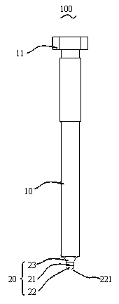
[0018] ginseng figure 1 As shown, the present invention provides a riveting machine, which includes: a riveting head 100, the riveting head 100 includes a main body 10 and a riveting portion 20 extending from the main body 10, the riveting portion 20 includes a riveting surface 221, The riveting surface 221 is spherical.

[0019] Of course, the riveting machine provided by the present invention also includes a power component that connects the riveting head 100 to provide power, a positioning component that defines the workpiece to be riveted, and a professional title power component and a bracket comp...


PUM


Abstract

The invention provides a riveting machine which comprises a rivet head. The rivet head comprises a main body portion and a riveting portion extending out from the main body portion, wherein the riveting portion comprises a riveting face, and the riveting face is a spherical face. Compared with the prior art, the riveting machine has the rivet head with a spherical front end, the spherical face makes contact with a rivet, the rivet punching efficiency is high, and work efficiency of the riveting machine is improved.

Description

technical field [0001] The invention relates to the field of mechanical processing equipment, in particular to a riveting machine. Background technique [0002] Riveting and welding are two well-known methods in the industry to connect multiple panels. Among them, riveting is a non-detachable connection that uses rivets to connect the riveted parts together. It has a long history of application in the field of building structures and machinery manufacturing. When riveting, first insert the rivet into the riveting hole of the riveted piece, and use the riveting head of the riveting machine to punch or roll the rivet to deform the rivet, thereby completing the riveting. [0003] The rivet heads in the existing riveting machines are all made of long straight metal rods, and the contact end with the rivet is a flat surface. During the contact process between the contact end of the flat surface and the rivet, the punching effect on the rivet is poor, resulting in low riveting eff...

Claims


Application Information

Patent Timeline
IPC IPC(8): B21J15/10
Inventor 沈皓然
Owner SIP GOLDWAY TECH
Why Eureka
Try Eureka