Conveniently-pushing-pulling type sensor molding extruding machine hopper

An extruder and sensor technology, applied in the field of sensor molding extruder hopper, can solve the problems of difficulty in changing material varieties, material residues, and labor intensity of workers, and achieve the effects of rapid replacement, avoiding material scattering, and facilitating material collection.

Inactive Publication Date: 2014-01-15
成都长迪传感技术有限公司
View PDF0 Cites 3 Cited by
  • Summary
  • Abstract
  • Description
  • Claims
  • Application Information

AI Technical Summary

Problems solved by technology

The chute is in the shape of a cuboid as a whole, with an opening on the surface and a cavity inside. The inner width of the chute is greater than the width of the opening. The cross section of the chute is in the shape of a "concave". , wherein, the lower slider is located inside the chute; the upper slider is located above the lower slider and outside the chute, the upper slider and the lower slider are connected by pipes, and the feed port of the extruder is arranged on the chute , the feed inlet is located at the bottom of the chute, the upper slider and the lower slider are passed through the pipe, the pipe connects the feed inlet and the hopper, and a handle is provided on the upper slider, so that when the material in the hopper needs to be replaced For varieties, use the handle to move the hopper body from the position of the feed port outward along the chute, so that the through hole of the lower slider can be connected with the discharge hole, which greatly facilitates the movement, removal, and replacement of the hopper body. It can clean the hopper body very well, discharge the material from the discharge hole, and fill the required material without removing the hopper body, avoiding high-intensity labor, and without turning the hopper body. Compared with the traditional hopper The structural form fixed on the extruder solves the problems of difficulty in changing material types, material residues, and high labor intensity of workers, and realizes the purpose of rapid replacement

Method used


Image

  • Conveniently-pushing-pulling type sensor molding extruding machine hopper

Examples


Embodiment

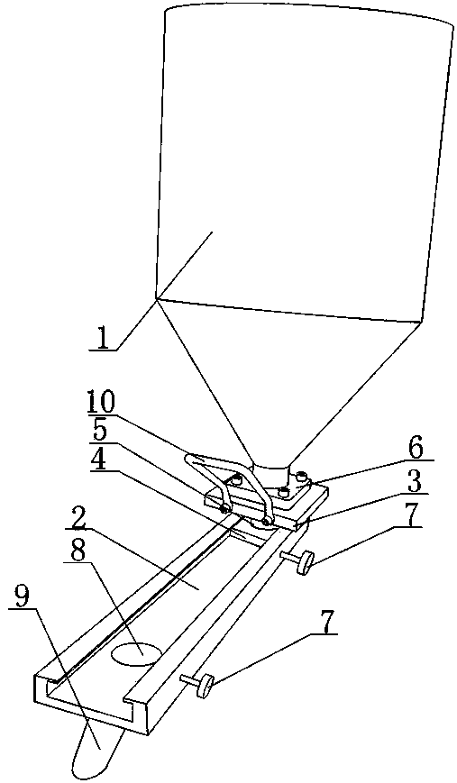
[0020] Such as figure 1 As shown, the push-pull sensor molding extruder hopper of the present invention includes a hopper body 1, and the hopper body 1 includes a cylindrical storage barrel, and a funnel-shaped discharge structure is connected to the bottom of the storage barrel; it also includes a fixed installation The chute 2 on the extruder is a rectangular parallelepiped as a whole, with an opening on the surface and a cavity inside. The inner width of the chute 2 is greater than the width of the opening, and the cross section of the chute 2 is "concave". 2 The bottom is provided with a feeding port connected with the extruder, and a lower slider 4 is installed in the chute 2, and two locking bolts 7 are arranged on the side of the chute 2, and the two locking bolts 7 are respectively connected with the feeding port and the Corresponding to the discharge hole 8, an upper slider 3 is installed above the lower slider 4, and the upper slider 3 is located above the chute 2, a...


PUM


Abstract

The invention discloses a conveniently-pushing-pulling type sensor molding extruding machine hopper. The conveniently-pushing-pulling type sensor molding extruding machine hopper comprises a hopper body and further comprises a slide groove fixedly formed in the extruding machine, wherein the inner width of the slide groove is greater than the opening width of the slide groove; a feeding opening communicated with the extruding machine is formed in the bottom of the slide groove; an upper slide block and a lower slide block are mounted below the hopper body, are located inside and outside the slide groove respectively, and are connected by a pipeline; the pipeline is used for communicating an inner cavity of the hopper body with the feeding opening; the upper slide block is provided with a handle. According to the conveniently-pushing-pulling type sensor molding extruding machine hopper, the upper slide block is provided with the handle so as to facilitate the movement, the taking out and the replacement of the hopper body and the hopper body can be cleaned very well; compared with a structural form of fixing a traditional hopper on the extruding machine, the hopper has the advantages that the problems that the varieties of materials are difficult to replace, the materials are remained and the labor intensity of workers is high are solved, and the aim of rapidly replacing is realized.

Description

technical field [0001] The invention relates to a hopper of an extruder in the sensor manufacturing industry, in particular to a sensor forming extruder hopper that is easy to push and pull. Background technique [0002] The automobile wheel speed sensor is mainly composed of induction head, wiring harness and accessories. The role of the induction head is to cooperate with the target gear installed on the chassis of the car to measure the speed of the car wheel, which is composed of coils, magnetic poles and other parts. On this basis, to ensure the normal operation of the sensor, the sensor must be properly installed on the chassis of the car, and there are many ways to install it. Now commonly used a kind of wheel speed sensor is to rely on the outer steel casing of the induction head to cooperate with a part, i.e. the elastic bush, and pack into the corresponding mounting hole of the chassis. When designing the sensor, it is necessary to combine the magnetic steel and ...

Claims


Application Information

Patent Timeline
Patent Type & Authority Applications(China)
IPC IPC(8): B29C47/10
CPCB29C48/29
Inventor 杨和荣
Owner 成都长迪传感技术有限公司
Why Eureka
Try Eureka