
Light guide plate

A light guide plate, light source technology, applied in optics, light guides, optical components, etc., can solve the problems of high manufacturing cost, prominent hot spot phenomenon, complex structure, etc.

Inactive Publication Date: 2014-01-15
NANJING GAOYIZHI PHOTOELECTRIC
View PDF5 Cites 1 Cited by
  • Summary
  • Abstract
  • Description
  • Claims
  • Application Information

AI Technical Summary

Problems solved by technology

This kind of structure is relatively complicated, the manufacturing cost is high, and it puts forward very high requirements on the placement of the follow-up light source 200
Moreover, if the position of the light source 200 is placed in an incorrect position or the position of the first field 141 and the second field 142 deviates during processing, the hot spot phenomenon will be more prominent

Method used


Image

  • Light guide plate
  • Light guide plate
  • Light guide plate

Examples


Embodiment Construction

[0042] Hereinafter, the present invention will be described in detail with reference to the accompanying drawings.

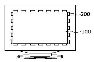
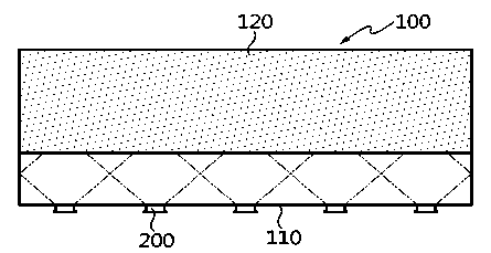
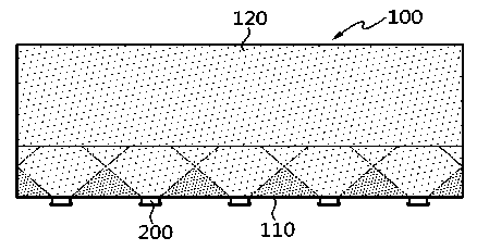
[0043] Such as figure 2 As shown: the light sources are placed on one side of the light guide plate 100 at a certain interval; a first concave hole structure 120 is provided in a region at a certain distance from the light incident surface 110 . The concave hole structure is composed of a plurality of concave holes located inside the light guide plate, that is to say, the concave holes are located on the surface (front surface or rear surface) of the light guide plate.

[0044] That is, a plurality of light sources 200 are placed at one side of the light guide plate 100 at certain intervals so that light enters from one side of the light guide plate 100 . The light source 200 uses LEDs, and the surface that allows light to enter the inside of the light guide plate 100 is called a light-incoming surface. In the light guide plate 100 , a first concave hole stru...


PUM

PropertyMeasurementUnit
Widthaaaaaaaaaa

Abstract

The invention relates to a light guide plate which comprises a light incoming face and a first concave hole structure. The light incoming face is arranged on the periphery of the light guide plate, the first concave hole structure is formed in the center area of the light guide plate, a second concave hole structure is formed between the light incoming face and the first concave hole structure, and the density of concave holes of the second concave hole structure in the length direction is same. The light reflection efficiency is improved due to the fact that the second concave hole structure is additionally arranged, and the problem of the hot spot phenomenon is effectively solved. The density of the concave holes of the second concave hole structure in the length direction is same, so that the light guide plate is convenient to machine, and the manufacturing cost of the light guide plate is saved. The density of the concave holes of the second concave hole structure in the length direction is same, so that the placing position of a light source placed below the light incoming face is not limited by the second concave hole structure.

Description

technical field [0001] The present invention relates to the light guide plate, specifically, to the reflective structure inside the light guide plate. Background technique [0002] Generally speaking, according to the way of light incident, the light guide plate can be divided into side incident light type and direct light type. The side light type is to place the light source (LED light) on the side of the light guide plate; the direct type is to place the light source (LED, etc.) under the light guide plate. The side-illuminated type is easier to manufacture than the direct-lit type, and is thinner and lighter, and because it uses fewer light sources, the manufacturing cost and use cost are lower. Due to the above characteristics, the side-illuminated type is widely used. [0003] Such as Figure 1a As shown: there are fewer light sources placed around the light guide plate 100 . In order to diffuse light into...

Claims


Application Information

Patent Timeline
IPC IPC(8): F21V7/10F21V8/00
Inventor 赵宰亨
Owner NANJING GAOYIZHI PHOTOELECTRIC
Learn More