Photographic device

A camera device and housing technology, applied in photography, image communication, television, etc., can solve the problems of inconvenient adjustment of auxiliary light sources, insufficient brightness of the monitoring range, and inability to obtain images by surveillance cameras, so as to achieve the effect of improving lighting and imaging effects

Inactive Publication Date: 2014-01-15
VIVOTEK INC
View PDF6 Cites 7 Cited by
  • Summary
  • Abstract
  • Description
  • Claims
  • Application Information

AI Technical Summary

Problems solved by technology

[0005] However, in the surveillance cameras of the prior art, when the irradiation range of the auxiliary light source needs to be changed, the user must manually adjust the irradiation range of the auxiliary light source.
This method of manually adjusting the irradiation range of the auxiliary light source creates the problem of inconvenient adjustment of the auxiliary light source
At the same time, when the monitoring camera changes the monitoring range, the auxiliary light source cannot be adjusted automatically, resulting in insufficient brightness of the monitoring range, and the monitoring camera cannot obtain a clear image
Therefore, surveillance cameras cannot achieve good imaging results

Method used


Image

  • Photographic device
  • Photographic device
  • Photographic device

Examples


no. 1 example

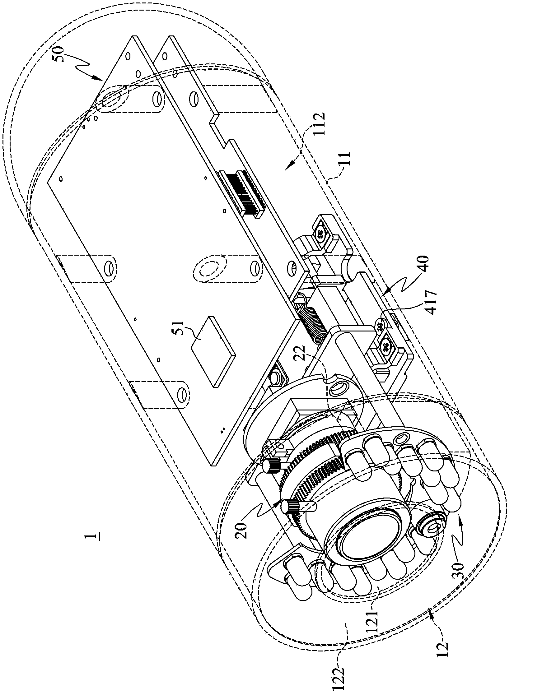
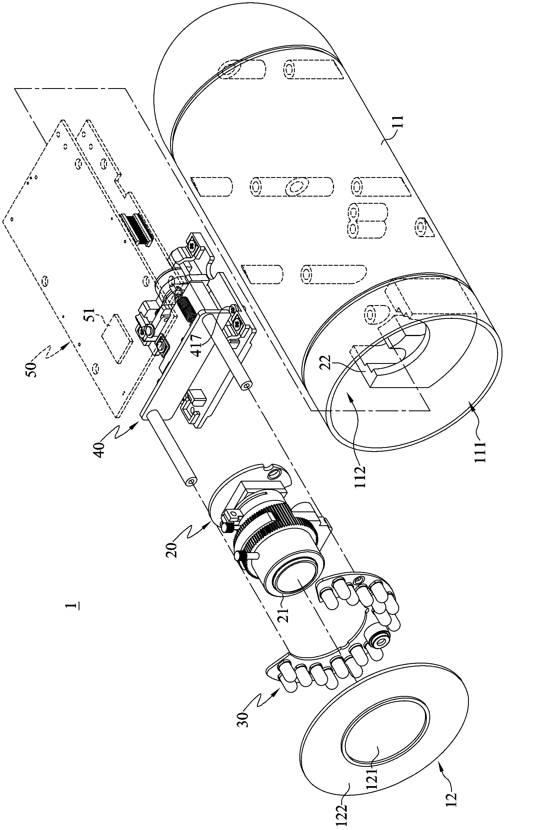
[0090] Please also refer to Image 6 as well as Figure 7 , Image 6 It is a three-dimensional perspective schematic view of the camera device according to the second embodiment disclosed in the present invention. Figure 7 for Image 6 An exploded schematic diagram of the camera setup. The elements of this embodiment are similar to the structure of the first embodiment, so the same symbols denote similar structures. In this embodiment, the imaging device 1' includes a housing 11, an imaging body 20, an auxiliary light source 30, a lens group 12 and an adjustment mechanism 40. Compared with the first embodiment, the auxiliary light source 30 of this embodiment is fixed on the surface 221 of the frame body 22 , but it is not intended to limit the present invention. In other embodiments, the auxiliary light source 30 can be fixed on the camera subject 20 .

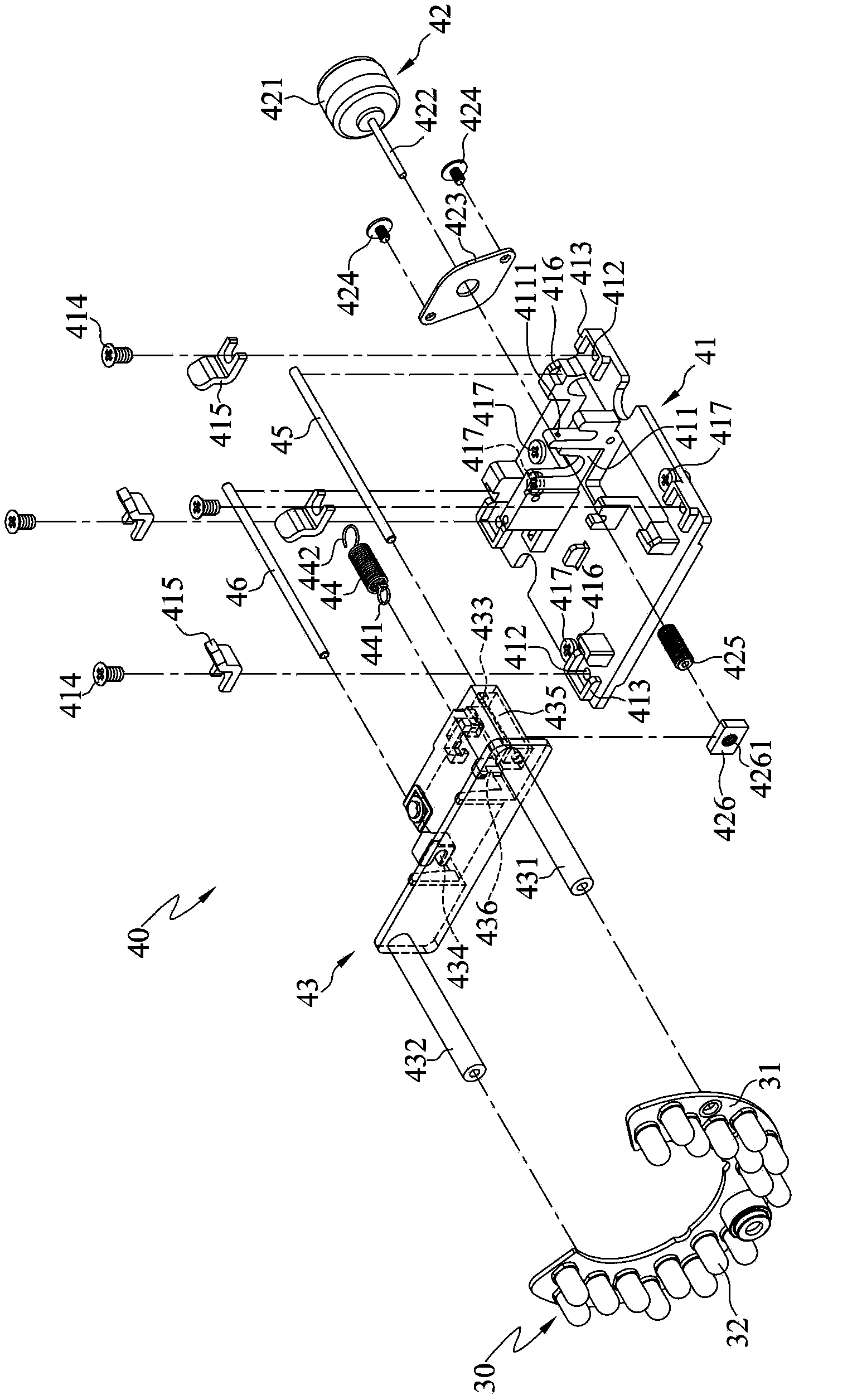
[0091] In this embodiment, the adjusting mechanism 40 includes a base plate 41 , a driving component 42 and a connecti...


PUM


Abstract

A photographic device includes a casing, a photographic body, an auxiliary light source and an adjusting assembly. The casing includes an opening. The photographic body, disposed in the casing, corresponds to the opening. The auxiliary light source, disposed between the casing and the photographic body, is used for emitting light outside through the opening. The adjusting assembly, disposed in the casing and connected to the auxiliary light source, is used for driving the auxiliary light source to move relative to the opening. In another embodiment, the photographic device includes a lens group arranged in the opening. The adjusting assembly is connected with the lens group to drive the lens group to move relative to the auxiliary light source. Through the photographic device, the auxiliary light source or the lens group is driven by the adjusing assembly to move relative to the opening, such that an irridiation scope and an irridiation angle of the auxiliary light source are changed to improve illumination and image capture effects.

Description

technical field [0001] The invention relates to an imaging device, in particular to an imaging device with an adjustable auxiliary light source. Background technique [0002] In recent years, surveillance cameras have been widely used in security monitoring. No matter in homes, businesses, government agencies, or even general public places, surveillance cameras have become an indispensable monitoring tool for personal safety and property protection. Generally speaking, surveillance cameras can monitor the dynamics of a monitoring environment, so as to grasp the occurrence of special events at any time. Therefore, when a special event occurs, the user can detect the occurrence of the event through the surveillance camera, or the surveillance camera can automatically notify the user, so that the user can deal with the special event immediately. [0003] In the prior art, in order to clearly monitor the dynamics of the monitoring environment, the surveillance camera may inclu...

Claims


Application Information

Patent Timeline
Patent Type & Authority Applications(China)
IPC IPC(8): H04N5/225G03B15/05
CPCG03B15/05G03B2215/0567H04N23/56H04N23/55G03B15/02
Inventor 马仕毅黄仲雍
Owner VIVOTEK INC
Why Eureka
Try Eureka