

Split application method for seed manure
A fertilizer and seed technology, applied in the field of separate application of fertilizers, can solve the problems of low fertilizer utilization rate, high labor intensity, complicated operation, etc., and achieve the effect of avoiding fertilizer waste, reducing labor intensity, and simple and convenient operation
- Summary
- Abstract
- Description
- Claims
- Application Information
AI Technical Summary
Problems solved by technology
Method used
Image

Examples
Embodiment Construction
[0023] The present invention will be further described below in conjunction with drawings and embodiments.
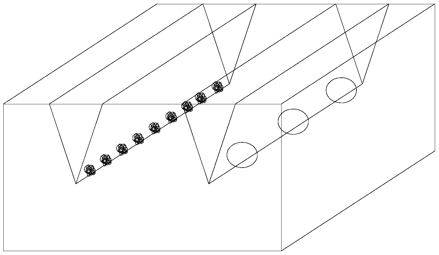
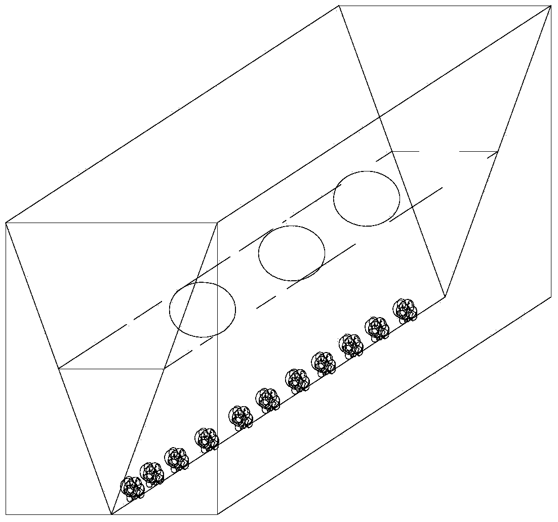
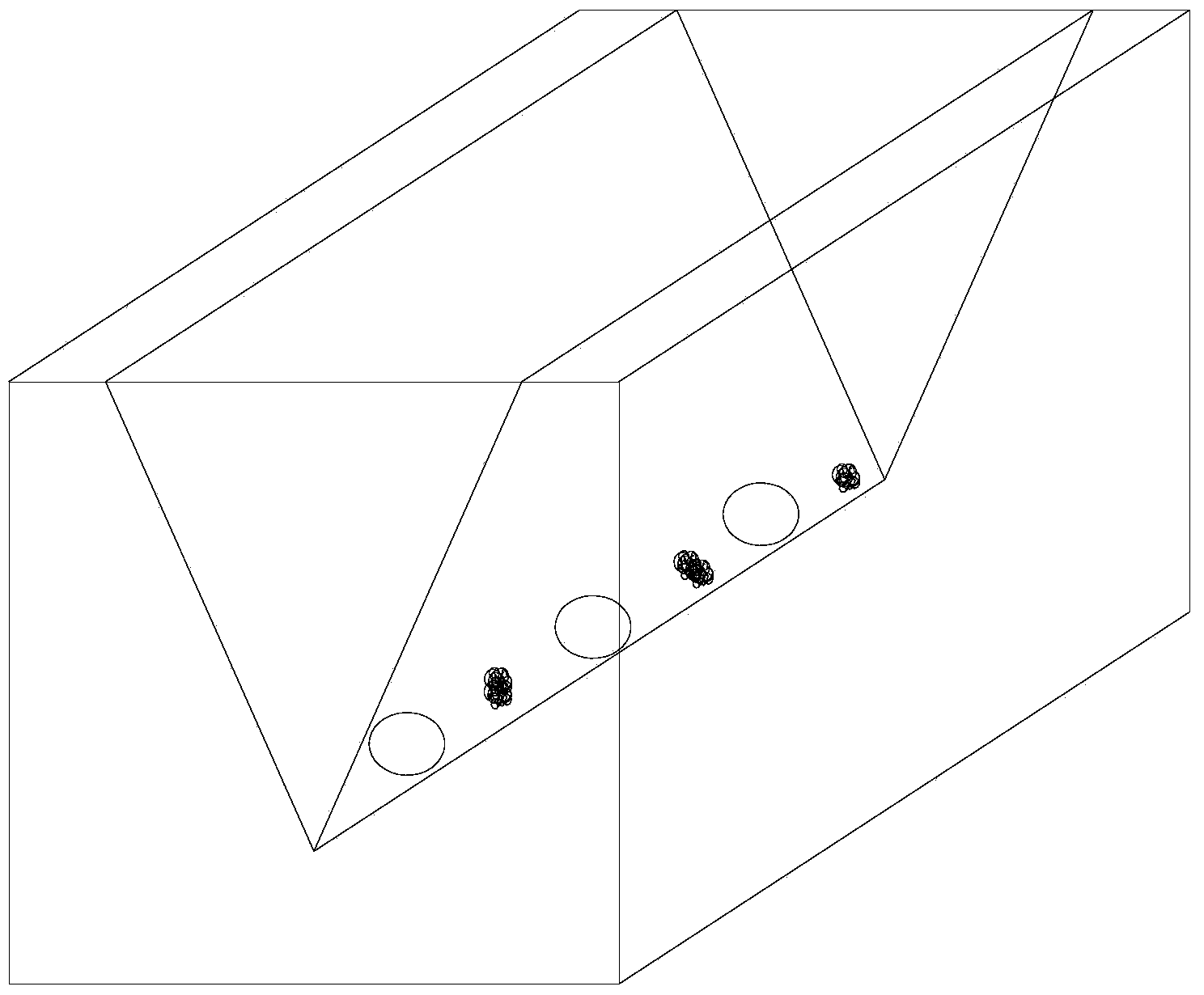
[0024] Such as image 3 Shown a kind of fertilization method, comprises the following steps:
[0025] (1) Use a ditch opener to open a planting ditch on the farmland, and the depth of the planting ditch is 5cm;
[0026] (2) Use a seed fertilizer dispenser to alternately place seeds and fertilizers in the planting ditch, with a certain distance between the seeds and fertilizers.
[0027] The distance between the seeds and the fertilizer is 10cm-20cm. Specifically, the distance between the seed and the fertilizer is determined according to the actual situation. And the distance between the seed and the fertilizer can be controlled by the horizontal movement speed of the fertilizer applicator and the fertilizer delivery wheel. For example, when using corn seeds, the distance between the corn seeds and the fertilizer is 15mm. That is, the present embodiment is preferab...
PUM
| Property | Measurement | Unit |
|---|---|---|
| Depth | aaaaa | aaaaa |
| Groove width | aaaaa | aaaaa |
Abstract
Description
Claims
Application Information