Manual jettisoning system of landing gear

A landing gear and handle technology, applied in the field of landing gear manual release system, can solve the problem that the aircraft cannot put down the landing gear

Inactive Publication Date: 2014-01-22
HARBIN
View PDF5 Cites 10 Cited by
  • Summary
  • Abstract
  • Description
  • Claims
  • Application Information

AI Technical Summary

Problems solved by technology

[0002] The existing aircraft landing gear throwing system mostly uses a hydraulic system. Once the hydraulic system fails, the aircraft will not be able to lower the landing gear

Method used


Image

  • Manual jettisoning system of landing gear
  • Manual jettisoning system of landing gear
  • Manual jettisoning system of landing gear

Examples


Embodiment Construction

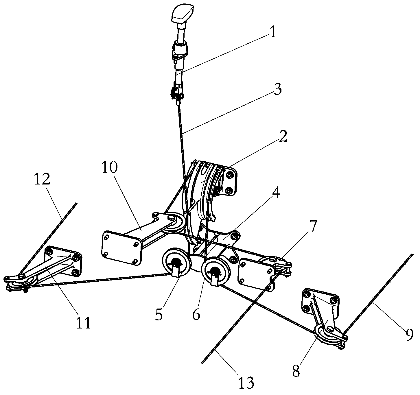
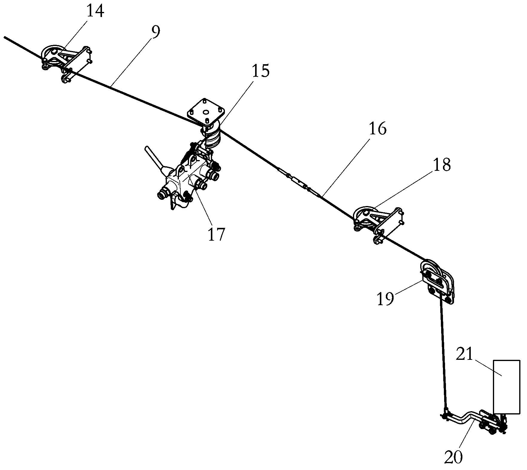
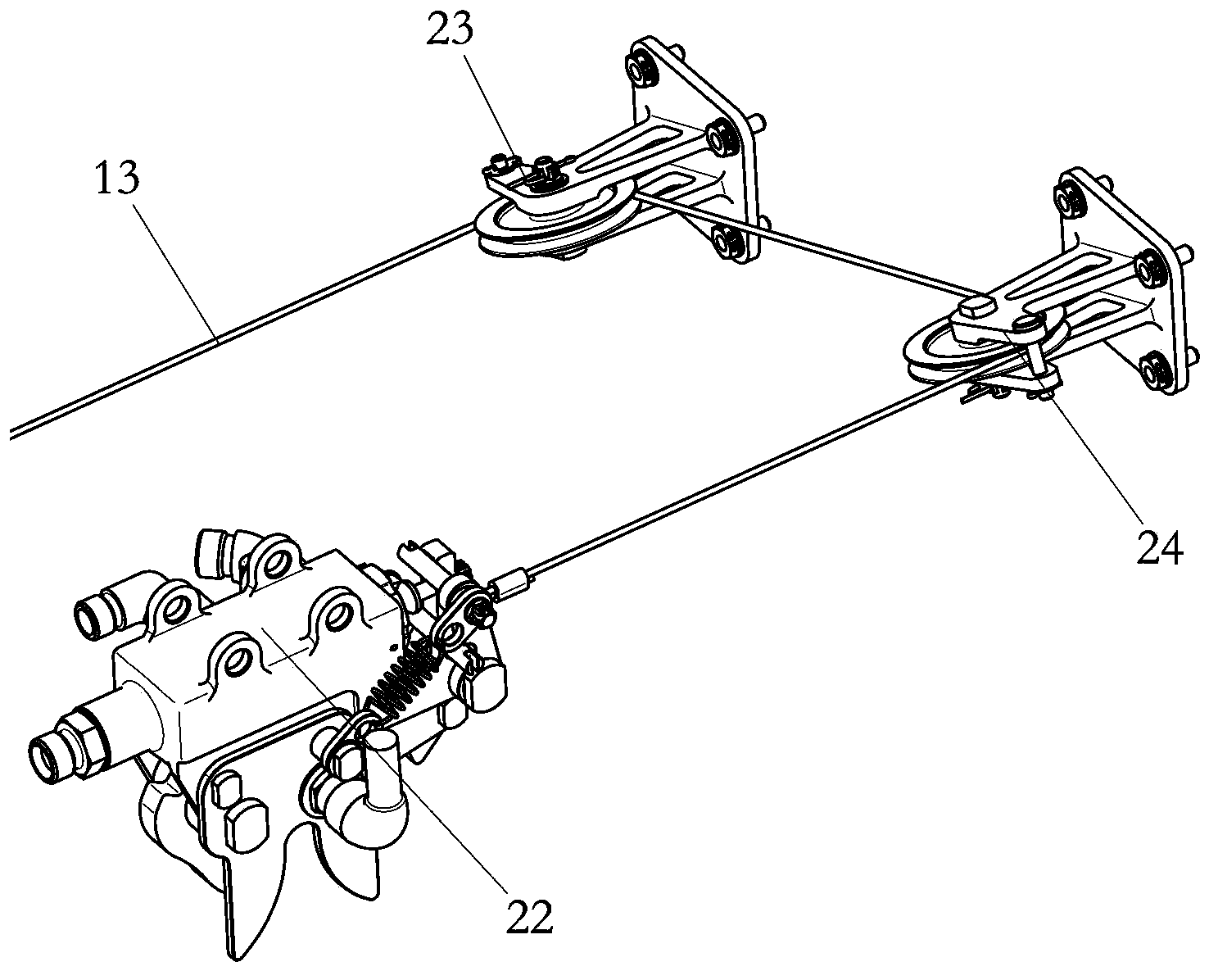
[0015] Such as Figure 1 to Figure 5 As shown, a landing gear manual release system of the present invention includes a landing gear manual release handle 1, a first steel cable 3, a second steel cable 9, a third steel cable 12, a fourth steel cable 13, and a fifth steel cable. Cable 16, first sector 2, second sector 15, support 4, first pulley 5, second pulley 6, first support pulley assembly 7, second support pulley assembly 8, third pulley support assembly 10, the first Four support pulley assemblies 11, the fifth support pulley assembly 14, the sixth support pulley assembly 18, the seventh support pulley assembly 19, the eighth support pulley assembly 23, the ninth support pulley assembly 24, the support rocker arm assembly 20.

[0016] The first sector 2 passes through the unlocking of the support 4, the second pulley 6, the second support pulley assembly 8, the fifth support pulley assembly 14, the second steel cable 9, the second sector 15 and the upper lock 17 of the l...


PUM


Abstract

The invention relates to the field of manufacturing of aircrafts, and provides a manual jettisoning system of a landing gear. A first fan-shaped member is connected with an unlocking rocker arm of a left main landing gear uplock through a bracket, a second pulley, a second bracket pulley assembly, a fifth bracket pulley assembly, a second steel rope and a second fan-shaped member; the second fan-shaped member is connected with a jettisoning valve through a fifth steel rope, a sixth bracket pulley assembly, a seventh bracket pulley assembly and a bracket rocker arm assembly; the first fan-shaped member is connected with an unlocking rocker arm of a right main landing gear uplock through the bracket, a first pulley, a fourth bracket pulley assembly and a third steel rope, and is connected with an unlocking rocker arm of a front landing gear uplock through a third bracket pulley assembly, a first bracket pulley assembly, a fourth steel rope, an eighth bracket pulley assembly and a ninth bracket pulley assembly. According to the manual jettisoning system of the landing gear, the landing gear is emergently put down when a hydraulic system fails.

Description

technical field [0001] The invention relates to the field of aircraft manufacturing, in particular to a landing gear manual ejection system. Background technique [0002] Existing aircraft landing gear throwing systems mostly use hydraulic systems. Once the hydraulic system fails, the aircraft will not be able to lower the landing gear. Contents of the invention [0003] The technical problem to be solved by the present invention is to provide a manual release system for the landing gear, which can drop the landing gear in an emergency when the hydraulic system fails. [0004] The technical scheme of the present invention is: a landing gear manual release system, comprising a landing gear manual release handle, a first steel cable, a second steel cable, a third steel cable, a fourth steel cable, a fifth steel cable, a A sector, a second sector, a bracket, a first pulley, a second pulley, a first bracket pulley assembly, a second bracket pulley assembly, a third pulley bra...

Claims


Application Information

Patent Timeline
Patent Type & Authority Applications(China)
IPC IPC(8): B64C25/20B64C25/30
Inventor 刘双宋宪龙季茂龄刁飞萌王永和宋彦南
Owner HARBIN
Why Eureka
Try Eureka