

Vacuum absorption conveying belt
A technology of vacuum adsorption and conveyor belt, applied in the field of conveyor belt, can solve the problem of not taking into account continuous conveying and vacuum adsorption, and achieve the effect of solving slippage and deformation and improving transmission efficiency
- Summary
- Abstract
- Description
- Claims
- Application Information
AI Technical Summary
Problems solved by technology
Method used
Image

Examples
Embodiment 1
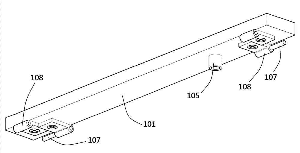
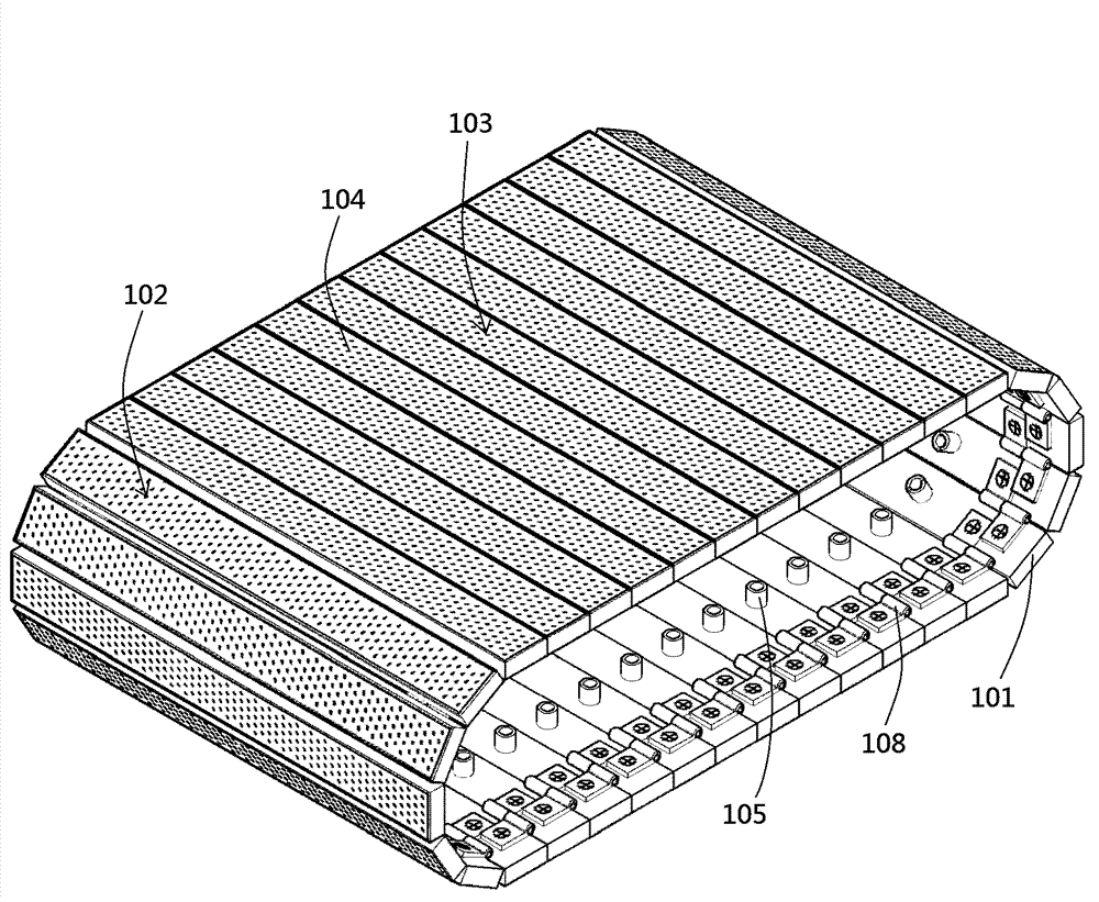
[0029] Example 1: See attached figure 1 And figure 2 , The hinge sleeve 108 is fixed on the vacuum suction unit 101, and the hinge pin 107 connects the vacuum suction units 101 to each other through the hinge sleeve 108 to form a vacuum suction conveyor belt. A regular polygonal rotating shaft can be used to support and tension the vacuum suction conveyor belt, so that the upward suction surface 102 is combined into the load surface 103. The regular polygon shaft can also directly drive the vacuum suction conveyor belt to rotate.
[0030] With the rotation of the vacuum suction conveyor belt, the suction surface 102 at one end of the loading surface 103 is continuously detached from the loading surface 103, while the suction surface 102 at the other end of the loading surface 103 is continuously replenished to the loading surface 103, thereby achieving continuous Conveying function.
[0031] The suction chamber inside the vacuum suction unit 101 communicates with the suction hole...
Embodiment 2
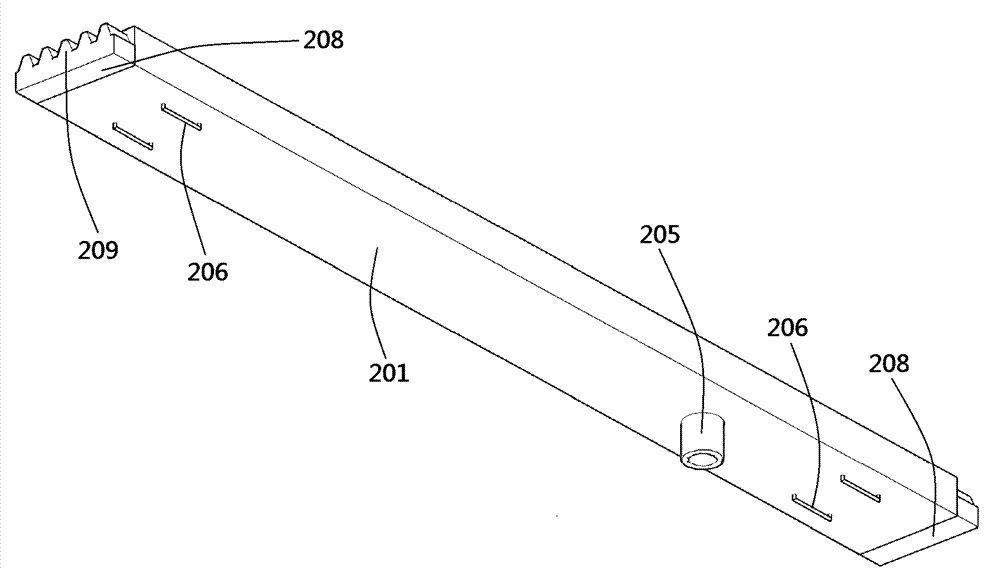
[0032] Example 2: See attached image 3 And Figure 4 , The vacuum suction unit 201 is fixed on the belt 207 by a fastener 206 to form a vacuum suction conveyor belt. The guide rail 210 supports the two ends of the vacuum suction unit 201 located in the conveying area through the reference surface 208, so that the suction surface 202 of the conveying area is combined into a flat load surface 203.
[0033] Both ends of the vacuum suction conveyor belt can be supported by a regular polygonal shaft, and assist the rotation of the vacuum suction conveyor belt.
[0034] The gear drives the vacuum suction conveyor belt to rotate through the rack 209. With the rotation of the vacuum suction conveyor belt, the suction surface 202 at one end of the loading surface 203 is continuously separated from the loading surface 203, and at the same time the suction surface at the other end of the loading surface 203 202 is continuously added to the load surface 203 to realize the continuous conveying...
Embodiment 3
[0036] Example 3: See attached Figure 5 And Image 6 The vacuum suction unit 301 is fixed on the chain 308 by a pin 307 to form a vacuum suction conveyor belt. The threads 309 at both ends of the vacuum suction unit 301 in the conveying area are matched with the threads on the screw rod 310.
[0037] The screw rod 310 serves as a limiter here, so that the suction surface 302 is combined into a flat load surface 303. Both ends of the vacuum suction conveyor belt can be supported by gears through the chain 308 to assist the rotation of the vacuum suction conveyor belt.
[0038] The rotation of the screw 310 can drive the vacuum suction conveyor belt to rotate. With the rotation of the vacuum suction conveyor belt, the suction surface 302 at one end of the loading surface 303 is continuously separated from the loading surface 303, and at the same time the suction surface at the other end of the loading surface 303 302 is constantly added to the loading surface 303, so as to realize t...
PUM
 Abstract
Description
Claims
Application Information