Supercharge Your Innovation With Domain-Expert AI Agents!

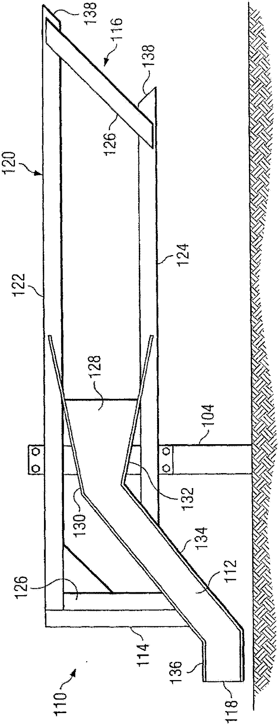
Guardrail safety system for dissipating energy to decelerate the impacting vehicle

一种安全系统、护栏的技术,应用在道路安全装置、道路、建筑等方向,能够解决系统不能保持张紧状态等问题

Active Publication Date: 2014-01-22
TEXAS A&M UNIVERSITY
View PDF6 Cites 1 Cited by
  • Summary
  • Abstract
  • Description
  • Claims
  • Application Information

AI Technical Summary

Problems solved by technology

These systems cannot be kept under tension during head-on and reverse-type impacts

Method used


Image

  • Guardrail safety system for dissipating energy to decelerate the impacting vehicle
  • Guardrail safety system for dissipating energy to decelerate the impacting vehicle
  • Guardrail safety system for dissipating energy to decelerate the impacting vehicle

Examples


Embodiment Construction

[0027] Existing guardrail end measures have proven to be unsafe for certain crash conditions occurring on highways, sensitive to installation details, and / or very expensive. However, the terminal measures described below are safety measures for the ends of W-beam barriers that provide higher performance levels over a wider range of crash conditions, reducing the cost of terminal measures and the number of casualties associated with barrier terminal accidents. The described system maintains tension in the guardrail beam elements during both head-on impacts and redirection-type impacts. But when the system is hit in reverse near the terminal. The anchorage system can be slack to prevent vehicle instability or excessive deceleration.

[0028] figure 1 A guardrail safety system 100 incorporating certain aspects of the present invention is illustrated. Guardrail system 100 may be installed near a highway to protect vehicles, drivers, and passengers from various nuisances and haz...


PUM


Abstract

In accordance with a particular embodiment of the present invention, an end treatment of a guardrail safety system includes a terminal portion of a guardrail beam that has a downstream end and an upstream end. The terminal portion of the guardrail beam slopes from a first vertical height appropriate for redirecting an errant vehicle to a second vertical height proximate the surface of the ground at an upstream end of the terminal portion of the guardrail beam. A flattening portion forms a channel through which the terminal portion of the guardrail beam is disposed. A vertical dimension of the channel is greater at a downstream end of the flattening portion than at an upstream end of the flattening portion. An impact plate is connected to the flattening portion for engaging an impacting vehicle at an end of said guardrail beam. During an end-on impact, the impact plate and the flattening portion are advanced longitudinally along the guardrail in a downstream direction by the vehicle. The advancement of the impact plate and flattening portion dissipate energy to decelerate the impacting vehicle. As downstream portions of the guardrail beam are forced into the flattening portion, the guardrail is flattened vertically. In accordance with a particular embodiment of the present invention, a terminal portion of a guardrail safety system includes a terminal portion of a guardrail beam having a downstream end and upstream end. The terminal portion of the guardrail beam slopes from a height appropriate for redirecting an errant vehicle to a height proximate the surface of the ground at an upstream end of the terminal portion. Support posts are installed adjacent a roadway in spaced apart relation to one another and are coupled to the terminal portion of the guardrail beam. A terminal support post is installed adjacent the roadway at an upstream end of the end terminal. The terminal support post couples to an upstream end of the terminal portion of the guardrail beam by a resistive, tensile coupling that maintains tension in the terminal portion of the guardrail beam. The resistive, tensile coupling is maintained between the terminal support post and the guardrail beam during an end-on or re-directive impact by a vehicle. However, the resistive, tensile coupling between the terminal support post and the guardrail beam is released during a reverse-direction impact.

Description

[0001] This application is a divisional application based on the invention patent application with the filing date of May 5, 2009, the application number of 200980126179.2, and the title of the invention "Guardrail safety system for dissipating energy to decelerate impacting vehicles". technical field [0002] The present invention relates generally to treatment for W-beam guardrails; and more particularly to tensioned guardrail terminations for end-on or re-directive The crash energy of the car colliding with the end of the W-beam barrier is dissipated during the crash. Background technique [0003] There are hazards along most highways that can be very dangerous to motorists if the car leaves the highway. Guardrails are installed to reduce the severity of accidents caused by vehicles leaving the highway. The guardrails are mounted such that the beam elements are in tension to assist in redirection type impacts. However, guardrails may be installed so that the end of thes...

Claims


Application Information

Patent Timeline
Patent Type & Authority Applications(China)
IPC IPC(8): E01F15/04E01F15/14
CPCE01F15/143
Inventor 阿卡姆·Y·阿布-欧戴施迪安·C·奥博森罗杰·P·比利格D·兰斯·小布拉德尤金·C·布什
Owner TEXAS A&M UNIVERSITY
Features
  • R&D
  • Intellectual Property
  • Life Sciences
  • Materials
  • Tech Scout
  • Unparalleled Data Quality
  • Higher Quality Content
  • 60% Fewer Hallucinations
Learn More