Movable parking device

A parking device, mobile technology, applied in the field of mobile parking devices, can solve the problems of increasing the height of the garage, long time, increasing the construction cost of the garage, etc.

Inactive Publication Date: 2014-01-22
梁晓军
View PDF6 Cites 8 Cited by
  • Summary
  • Abstract
  • Description
  • Claims
  • Application Information

AI Technical Summary

Problems solved by technology

[0002] At present, the automobile industry is developing rapidly, and the difficulty of parking has become a focus of the public. At present, the structure of the indoor parking lot is mainly a frame type, with concrete pillars on both sides of the two-way lane, and two or more concrete pillars between the front and rear two concrete pillars. Three parking spaces perpendicular to the driveway. In order to facilitate the entry and exit of vehicles and parking, the width of the two-way driveway should be greater than the length of the vehicle, generally more than 6 meters. Therefore, a considerable part of the indoor parking lot is occupied by the driveway. In order to increase the number of parking lots At present, the technical solution of mechanical double-layer lifting and lateral movement is the most adopted. This technical solution requires that each vehicle needs a parking pallet, and each parking pallet is equipped with power, and must have lifting and lateral moving functions. The structure and technology are more complicated, the failure rate is high, and the parking and picking up of the car are more cumbersome, and the time is longer, and the car cannot be accessed in the power failure state; Increase the height of the garage and increase the construction cost of the garage. Therefore, it is possible to increase the number of parking spaces in the garage without increasing the construction cost of the garage. At the same time, it is possible to increase the number of parking spaces in the existing garage through simple mechanical devices. The above situation needs to be solved in the application of indoor parking lot technology

Method used


Image

  • Movable parking device
  • Movable parking device
  • Movable parking device

Examples


Embodiment Construction

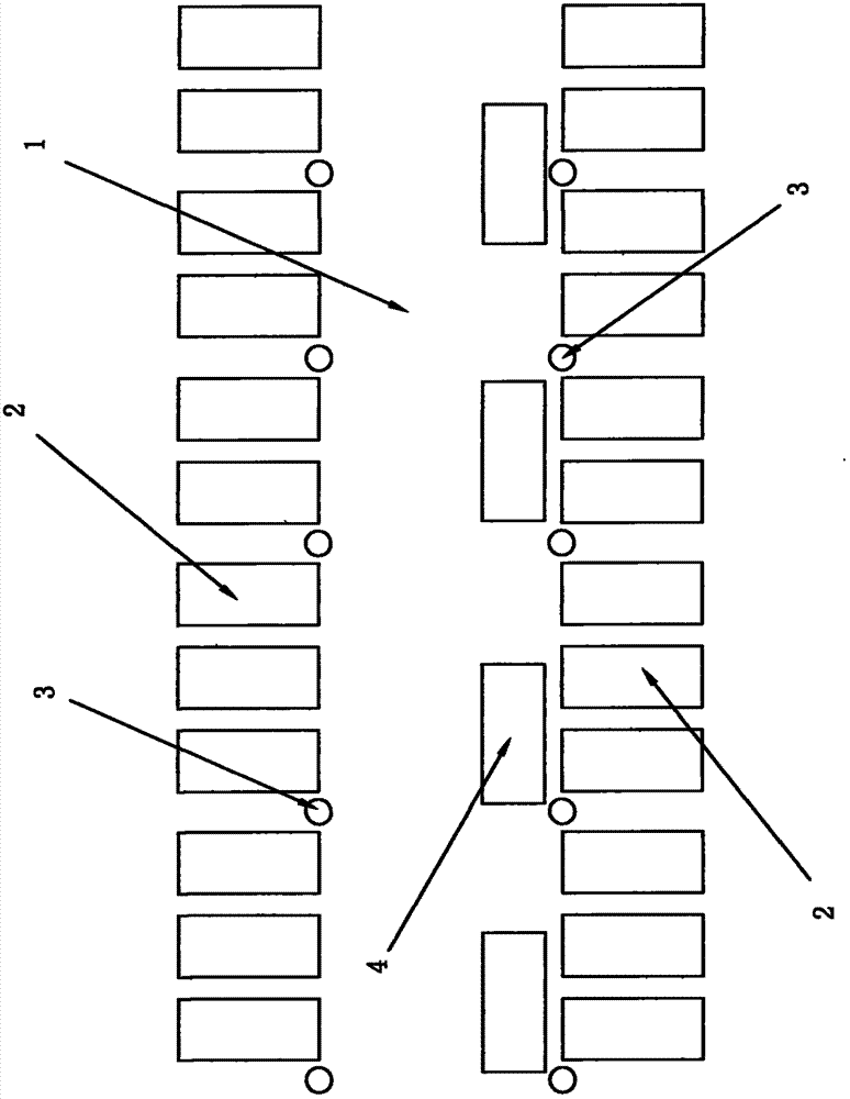
[0031] Such as figure 1 The schematic diagram of the working position of the mobile parking device is shown, the parking tray (4) is set on one side of the garage driving lane (1), and there are three parking spaces or two parking spaces respectively between the front and rear concrete pillars (3) , adjacent parking pallets (4) are separated by one parking space width, the length of the parking pallet (4) occupies the width of two parking spaces (2), and the parking pallet (4) moves forward or backward by one parking space during use width.

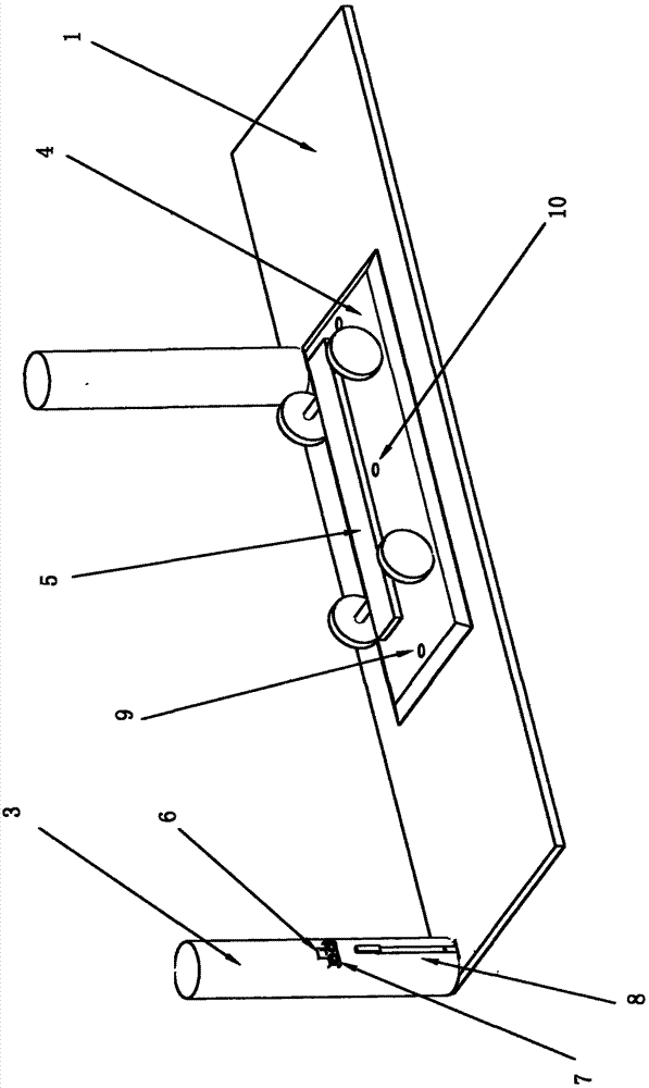
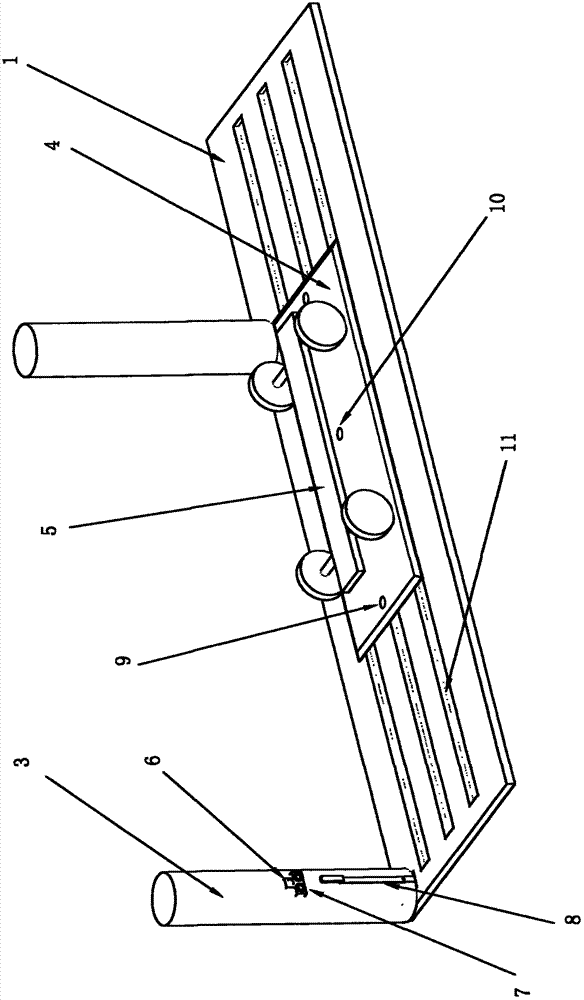
[0032] Such as diagram 2-1 The working schematic diagram of the planar mobile parking device is shown. A parking pallet (4) is provided on the driving lane (1), on which vehicles (5) are parked, and slopes are provided on the four sides of the parking pallet (4) to facilitate the passage of vehicles. , a vehicle position sensor (9) is respectively arranged on the front and rear end surfaces of the parking tray (4), the two ends of its ...


PUM


Abstract

Disclosed is a movable parking device. Parking spaces perpendicular to a driving lane are formed between a front concrete prop and a rear concrete prop on two sides of the driving lane of a garage, a rail groove is formed in a road surface on one side of the driving lane, rollers and a rack placed in the rail groove are arranged on two sides and in the middle of the back of a parking pallet respectively, a speed reducing motor is arranged in a groove of the ground below the parking pallet, a gear engaged with the rack at the back of the parking pallet is arranged on an output shaft of the speed reducing motor, the speed reducing motor drives the parking pallet to move front and back along the rail groove through the gear and the rack, and vehicles can be parked on the parking pallet. When the vehicles enter and exit the parking spaces, the parking pallet moves front and back along the driving lane by the aid of a control switch, and the parking pallet is unlocked to move by a manual pull rod in a power-off state. The number of the parking spaces can be increased at low cost on the basis that parking spaces are distributed in the indoor garage, and the movable parking device has the advantages of safety, reliability, low cost and easiness in implementation.

Description

technical field [0001] The invention relates to automobile parking technology, in particular to a mobile parking device. technical background [0002] At present, the automobile industry is developing rapidly, and the difficulty of parking has become a focus of the public. At present, the structure of the indoor parking lot is mainly a frame type, with concrete pillars on both sides of the two-way lane, and two or more concrete pillars between the front and rear two concrete pillars. Three parking spaces perpendicular to the driveway. In order to facilitate the entry and exit of vehicles and parking, the width of the two-way driveway should be greater than the length of the vehicle, generally more than 6 meters. Therefore, a considerable part of the indoor parking lot is occupied by the driveway. In order to increase the number of parking lots At present, the technical solution of mechanical double-layer lifting and lateral movement is the most adopted. This technical soluti...

Claims


Application Information

Patent Timeline
Patent Type & Authority Applications(China)
IPC IPC(8): E04H6/12
Inventor 梁晓军
Owner 梁晓军
Why Eureka
Try Eureka