Rotary parking device

A parking device and rotary technology, applied in the field of rotary parking devices, can solve problems such as cumbersome parking and picking up cars, increased garage construction costs, complex structures and technologies, etc.

Inactive Publication Date: 2014-01-22
梁晓军
View PDF7 Cites 5 Cited by
  • Summary
  • Abstract
  • Description
  • Claims
  • Application Information

AI Technical Summary

Problems solved by technology

[0002] At present, the automobile industry is developing rapidly, and parking difficulties have become a focus of the public. At present, the structure of the indoor parking lot is mainly a frame type, with concrete pillars on both sides of the two-way lane, and two or three pillars between the front and rear pillars. A parking space perpendicular to the driving lane, in order to facilitate the entry and exit of vehicles and parking, the width of the two-way driving lane is greater than the length of the vehicle, generally more than 6 meters, so a considerable part of the area of ​​the indoor parking lot is occupied by the driving lane, in order to increase The number of parking spaces is currently the most used technical solution of mechanical double-layer lifting and lateral movement. This technical solution requires that each vehicle needs a parking pallet, and each parking pallet is equipped with power, and must have lifting and lateral movement. The mobile function is relatively complicated in structure and technology, and the failure rate is high. At the same time, parking and picking up the car are more cumbersome and take a long time, and the vehicle cannot be accessed in a power failure state; The parking space needs to increase the height of the garage and increase the construction cost of the garage. Therefore, can the number of parking spaces in the garage be increased without increasing the construction cost of the garage, and at the same time, the parking space can be realized in the existing garage through simple mechanical devices? The above situation needs to be solved in the application of indoor parking lot technology

Method used


Image

  • Rotary parking device
  • Rotary parking device
  • Rotary parking device

Examples


Embodiment Construction

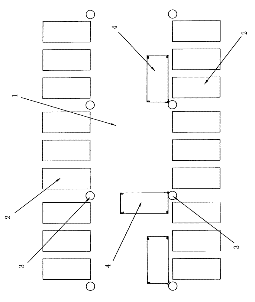
[0033] Such as figure 1 As shown in the plan view of the working position of the rotary parking device, three parking spaces (2) are respectively arranged between the front and rear concrete pillars (3), and the parking tray (4) is arranged on one side of the garage driving lane (1), and Hinged on a concrete pillar (3), adjacent parking pallets (4) are separated by the width of one parking space (2), and the length of the parking pallet (4) occupies the width of two parking spaces (2). (4) It can rotate 90° along the concrete pillar (3).

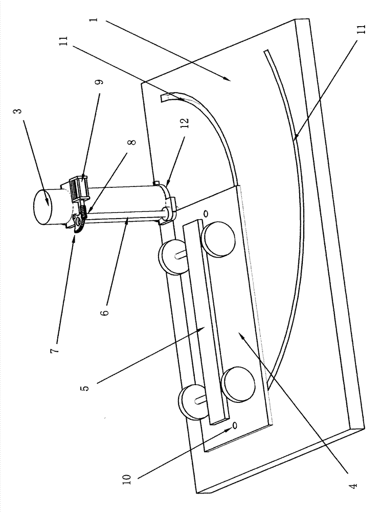
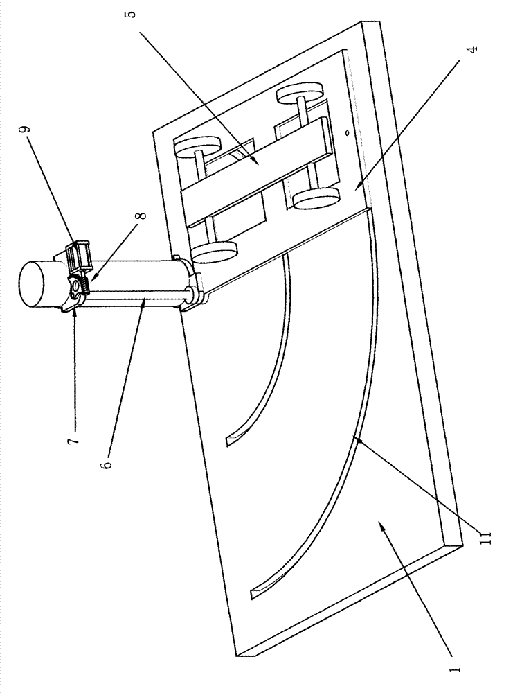
[0034] Such as figure 2 The working schematic diagram of the suspension-driven rotary parking device shown in the figure shows a fixed support (12) on the concrete pillar (3), which is hinged with a rotating arm (6), whose lower end is connected with a parking tray (4), and whose upper end is connected with There is a worm gear (7), a reduction motor (9) is arranged on the fixed bracket (12), and a worm (8) is arranged on its output shaft...


PUM


Abstract

Disclosed is a rotary parking device. Parking spaces perpendicular to a driving lane are formed between a front concrete prop and a rear concrete prop on two sides of the driving lane of a garage, a fixed support is arranged on the concrete prop on one side of the driving lane, a rotating arm is hinged onto the fixed support, the upper end of the fixed support is connected with a worm gear, a worm engaged with the worm gear is arranged on an output shaft of a speed reducing motor, the lower end of the rotating arm is connected with a parking pallet supported by rollers, an arc-shaped rail groove is formed in a road surface, the rollers are placed in the rail groove, the speed reducing motor drives the parking pallet to rotatably move along a rail through the worm and the worm gear, the parking pallet is hinged onto the rotating arm of the concrete prop, a vehicle is parked on the parking pallet, other vehicles rotatably move at a position parallel to the driving lane when entering and exiting the parking spaces, the number of the parking spaces can be increased at low cost on the basis that parking spaces are distributed in the indoor garage, and the rotary parking device has the advantages of safety, reliability, low cost and easiness in implementation.

Description

technical field [0001] The invention relates to automobile parking technology, in particular to a rotary parking device. technical background [0002] At present, the automobile industry is developing rapidly, and parking difficulties have become a focus of the public. At present, the structure of the indoor parking lot is mainly a frame type, with concrete pillars on both sides of the two-way lane, and two or three pillars between the front and rear pillars. A parking space perpendicular to the driving lane, in order to facilitate the entry and exit of vehicles and parking, the width of the two-way driving lane is greater than the length of the vehicle, generally more than 6 meters, so a considerable part of the area of ​​the indoor parking lot is occupied by the driving lane, in order to increase The number of parking spaces is currently the most used technical solution of mechanical double-layer lifting and lateral movement. This technical solution requires that each vehi...

Claims


Application Information

Patent Timeline
Patent Type & Authority Applications(China)
IPC IPC(8): E04H6/40
Inventor 梁晓军
Owner 梁晓军
Why Eureka
Try Eureka